BEST SELL

TMS320F28379DZWTT
Texas Instruments

Yes. APT26M100JCU2 by Microchip is available for RFQ. Submit your required quantity and our team will confirm real-time stock, lead time, and volume pricing.
Pricing for APT26M100JCU2 can vary by order quantity, market availability, date code, packaging, and delivery destination. Request a quote to receive the latest volume pricing.
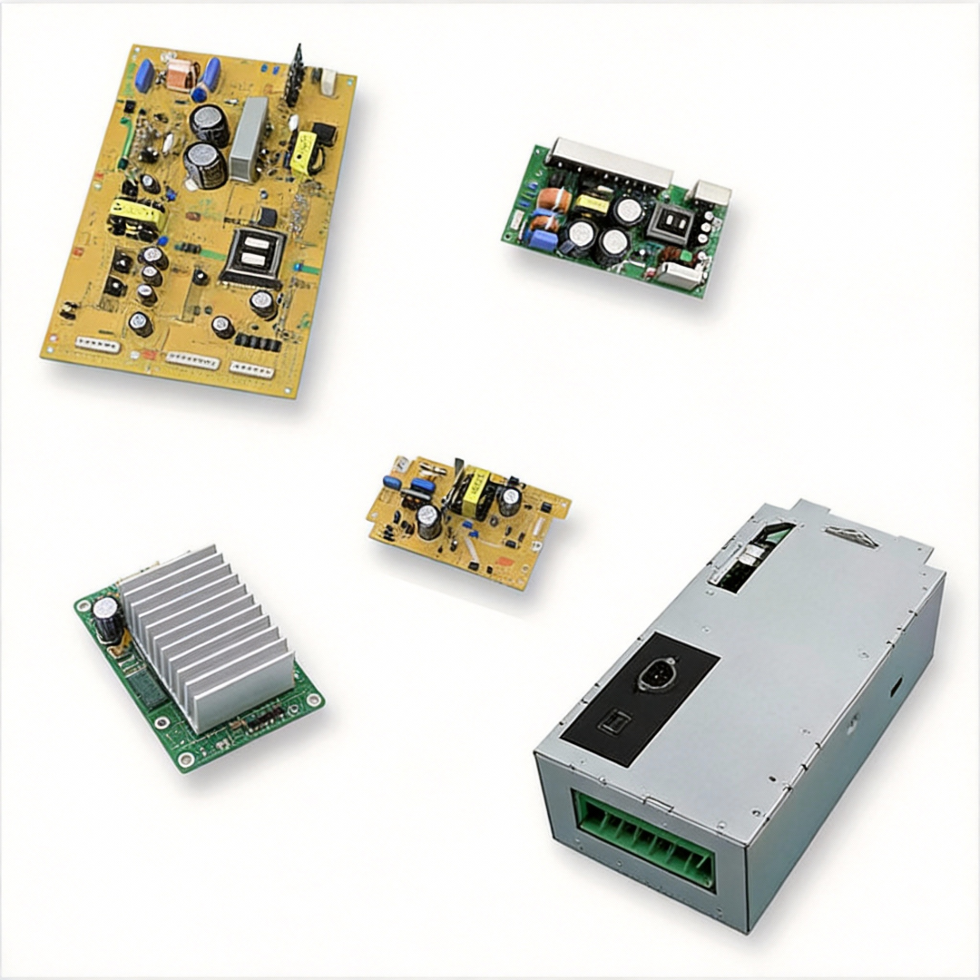
APT26M100JCU2 is a Microchip Power Supplies with Packaging: Bulk and Current - Continuous Drain (Id) @ 25°C: 26A Tc and Drive Voltage (Max Rds On,Min Rds On): 10V. Review the product details or submit an RFQ if you need confirmation before purchase.
Our sales team usually responds within 24 hours after receiving your RFQ. The quote may include stock status, unit price, lead time, shipping options, and available alternatives.
If stock is confirmed, in-stock parts can usually ship within 1–2 business days. Final lead time depends on quantity, stock source, and delivery destination.
Yes. If APT26M100JCU2 is unavailable, obsolete, or does not meet your required lead time, we can help check similar Microchip Power Supplies parts or compatible alternatives.
Looking for Pricing? Contact us for volume pricing.
Fast Dispatch: Ships in 5-7 days(in-stock parts within 1-2 days)
Unishop Global Export: 1-7 days, $40.00
Guaranteed Delivery: Door-to-door in 30 days
Compliant Worldwide Shipping: DHL, FedEx, SF, and UPS.


IMPORTANT NOTICE
Quotations are subject to stock availability and may vary with market conditions. Prices and lead times are not guaranteed until a purchase order is confirmed. Ensure your contact details are correct to avoid delays in response.
TMS320F28379DZWTT
Texas Instruments

MT47H128M16RT-25E IT:C
Micron

K4B2G1646F-BCNB
SAMSUNG
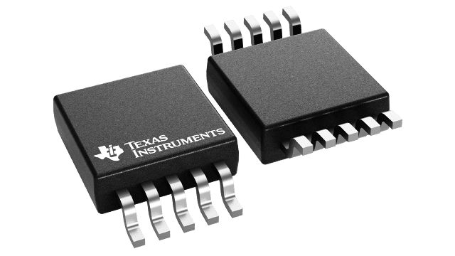
INA226AIDGSR
Texas Instruments
M25P80-VMW6TG
Micron
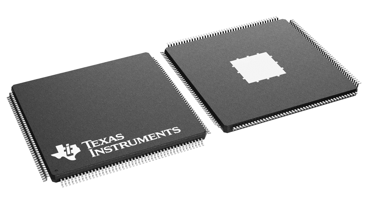
TMS320F28334ZJZS
Texas Instruments

UCC28070APW
Texas Instruments

K4AAG165WA-BCWE
SAMSUNG
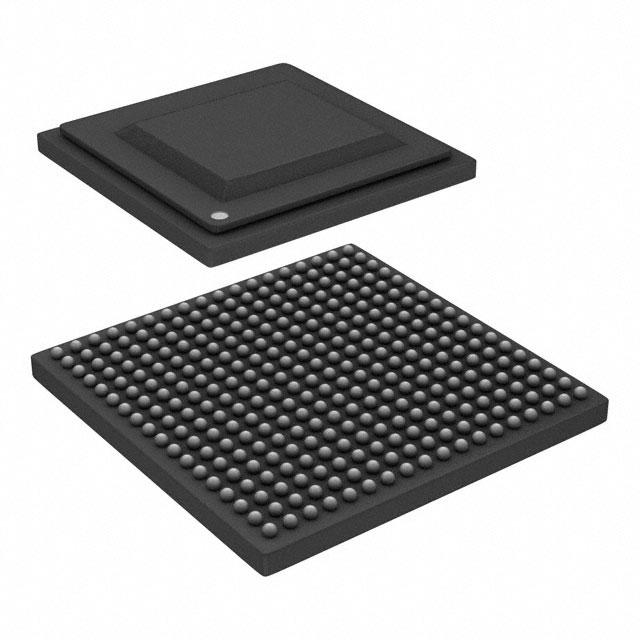
89H16NT16G2ZCHLG
RENESAS

ISL8215MIRZ
RENESAS
No recently viewed products