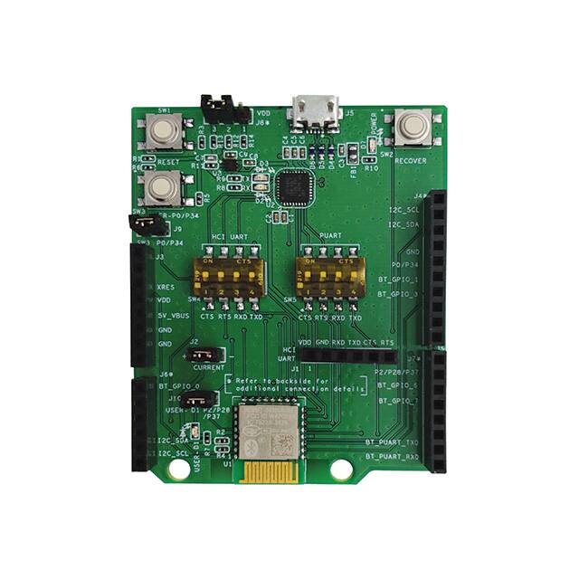
Electronic Devices and Circuits: From Parts to PCB
Electronic Devices and Circuits: Turn Parts into a Working PCB
Electronic devices perform useful work when their electrical connections, power sources and control signals form a coordinated circuit. Knowing a resistor from a transistor is a starting point. To build a working PCB, identify what each block consumes, what it produces and what the next block expects. That interface-based view helps expose problems that a list of component definitions misses.
Think in functions before choosing packages
A small sensor node offers a manageable example. Its power block supplies energy; a sensor converts a physical quantity into an electrical output; signal conditioning adapts that output; a processor interprets the result; and an indicator or driver acts on it. One integrated circuit may combine several functions, while another design separates them.
Analog, digital and mixed-signal describe how information is handled. Passive, semiconductor and electromechanical describe different aspects of the parts. These labels overlap rather than forming one clean set of alternatives. A relay, for example, has a coil requiring electrical power and contacts that switch another path. Its control interface matters more than forcing it into a single category.
Give each component a specific responsibility
A resistor can establish a current, divide a voltage or dissipate energy, depending on its connections. A capacitor stores electric-field energy and presents frequency-dependent impedance. An inductor stores magnetic-field energy and resists changes in current. Transistors can provide switching or amplification, while an integrated circuit combines devices to implement a more complex function.
Real parts add limits to ideal models. A capacitor's equivalent series resistance and inductance affect its behavior around and above self-resonance. Murata's explanation of capacitor impedance shows why a capacitance value alone cannot describe high-frequency performance. “Passes AC” is therefore a useful first approximation only within an appropriate frequency range and circuit context.
An inductor similarly needs more than an inductance label. DC resistance, current ratings, temperature and saturation behavior influence whether it fits an application. Coilcraft's introduction to inductor specifications distinguishes the checks needed to connect nominal inductance with operating conditions. Energy storage does not mean the physical component has zero loss.
Walk through a low-voltage sensor node
Imagine a battery-powered temperature indicator. Before drawing the PCB, assign a requirement to every connection. The sensor output must lie within the measurement input range. The processor supply must stay valid during startup and display activity. The indicator must draw a current that its driver can support.
For an illustrative LED branch, assume a 3.0 V source, a 1.8 V forward drop at the intended current and a 3 mA target. The calculated series resistance is (3.0 − 1.8) / 0.003 = 400 ohms. Choosing an illustrative 430-ohm value gives about 2.8 mA under those same assumptions. Its resistor dissipation is approximately 3.3 mW.
The arithmetic does not qualify an actual LED or output pin. Repeat it using the highest supply, lowest relevant forward voltage and resistor tolerance to estimate maximum current. Then check the driver's guaranteed behavior. This small example demonstrates the general workflow: define assumptions, calculate an interface, and compare the result with component limits.

Move from schematic connections to PCB geometry
A schematic tells you which nodes connect. A PCB also determines the length and position of those connections, their return paths and their proximity to other signals. Preserve the functional blocks while placing parts, but review the connections between blocks as carefully as the blocks themselves.
Check pin numbers against the intended package, identify polarized components, and provide accessible points for important rails and signals. Keep bypass components close to the pins they serve according to device guidance. Route high-current paths with their return paths in mind, and avoid making a sensitive measurement share an uncontrolled voltage drop with a load.
The fabrication drawing, bill of materials and placement data must describe the same design revision. A design-rule check evaluates the rules entered into the software; it cannot determine whether an incorrectly specified interface will function.
Test the circuit in an order that reveals causes
Begin with visual inspection and unpowered checks for unintended shorts. Apply power with an appropriate current limit and verify the rails before exercising the signal path. Confirm the sensor output, then the conditioned signal, then the processor's interpretation, and finally the indicator or load response.
That order creates useful evidence. If the sensor output is correct but the reported value is wrong, the search narrows to the measurement interface, conversion or software. If a rail collapses when the indicator turns on, investigate the power and return paths first. A successful assembly inspection does not replace these functional measurements.
Frequently asked questions
Is an integrated circuit the same thing as a PCB?
No. An integrated circuit contains electronic structures within a semiconductor device. A PCB provides connections and mechanical support for packaged components. A board may contain many ICs plus passive and electromechanical parts.
Why can the same schematic behave differently on two boards?
Layout changes parasitic resistance, inductance, capacitance and coupling. Component tolerances, assembly differences and power conditions also matter. Compare the physical implementation and measured interfaces rather than assuming that matching net names guarantees matching behavior.
Discuss Your Circuit's PCB Requirements
Share your PCB manufacturing or PCBA assembly requirements through icallin's quotation page.