Part number
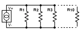
Calculate branch currents in parallel circuits using the current divider rule. Supports up to 10 resistors with instant, accurate results.
Introduction
Parallel circuits in which the source or supply current divides into a variety of parallel paths are known as current divider circuits. Both of the components in a parallel wired circuit have their terminals connected together and share the same two end nodes.
Parallel circuits are distinguished by the fact that, although different currents can flow through different branches, the voltage is shared by all linked paths. VR1 = VR2 = VR3... and so on. As a result, finding individual resistor voltages is no longer necessary, and branch currents can be easily calculated using Kirchhoff's Current Law (KCL) and, of course, Ohm's Law.
The current flowing through any branch of a parallel circuit can be calculated using this Current Divider Calculator.
When a circuit is connected in parallel, the total current from the power source is divided among the circuit's branches depending on the resistance values of each branch. Since current follows the path of least resistance, more current will flow through branches with lower resistance, while less current will flow through a branch with high resistance.
Understanding how current splits in a parallel circuit is essential for effective circuit design. Our calculator applies the standard Current Divider Rule to simplify this process for you.
To find the current flowing through a specific branch, we use the following equation:
Where:
The unit of this calculator's result is the one stated. Amperes (A), milliamperes (mA), or microamperes (A) may be used to express the resultant value.
Current dividers or current division is the process of finding the individual branch currents in a parallel circuit were each parallel element has the same voltage. Kirchhoff's current law, (KCL) states that the algebraic sum of the individual currents entering a junction or node will equal the currents leaving it.
Current Division Rule A parallel circuit acts as a current divider as the current divides in all the branches in a parallel circuit, and the voltage remains the same across them. The current division rule determines the current across the circuit impedance.
A voltage divider is applying a voltage across a series of two resistors. We may draw in a few different ways, but they should always essentially be the same circuit. Thus formula is given as follows: V o u t = R b R a + R b × V i n V_{out} = \frac{R_b}{R_a+R_b} \times V_{in} Vout=Ra+RbRb×Vin.
Ohms Law and Power To find the Voltage, ( V ) [ V = I x R ] V (volts) = I (amps) x R (Ω) To find the Current, ( I ) [ I = V ÷ R ] I (amps) = V (volts) ÷ R (Ω) To find the Resistance, ( R ) [ R = V ÷ I ] R (Ω) = V (volts) ÷ I (amps) To find the Power (P) [ P = V x I ] P (watts) = V (volts) x I (amps)
Application Dont's. As tempting as it may be to use a voltage divider to step down, say, a 12V power supply to 5V, voltage dividers should not be used to supply power to a load. Any current that the load requires is also going to have to run through R1.
"A parallel circuit has two or more paths for current to flow through." Simply remember that PARALLEL means two paths up to thousands of paths. The flow of electricity is divided between each according to the resistance along each route.
Divide the voltage by R1 to get I1. V/R1 = I1. I1 will be measured in amps. Divide the voltage by R2 to get I2.
Using the voltage divider ratio rule, we can see that the largest resistor produces the largest I*R voltage drop. Thus, R1 = 4V and R2 = 8V. Applying Kirchhoff's Voltage Law shows that the sum of the voltage drops around the resistive circuit is exactly equal to the supply voltage, as 4V + 8V = 12V.
A multimeter set to measure current can only measure the current going through it. ... Devices in parallel must have the same voltage across them, although the currents through each can be different.
ICAllIn’s Resistor Color Code Calculator is an interactive tool for identifying resistor values based on 4-band, 5-band, and 6-band color codes. Simply select the colors, and the calculator will display the resistance in Ohms (Ω), tolerance, and power rating. Whether you are building a circuit, repairing electronics, or sorting resistors in your lab, this calculator provides an accurate and efficient way to decode resistor values.
ICAllIn’s Ohm’s Law Calculator helps engineers and students quickly calculate resistance, current, voltage, and power in an electrical circuit. Simply enter any two known values, and the calculator will instantly compute the remaining parameters. This fast and easy-to-use online tool illustrates the fundamental relationship between voltage, current, and resistance, making it essential for circuit design, troubleshooting, and electronics learning.
The Op Amp Voltage and Gain Calculator is an easy-to-use tool for analyzing operational amplifier circuits. It calculates the output voltage, inverting gain, and non-inverting gain based on the input parameters. Simply enter the values of V1, V2, Vp, Vn, and the resistor values R1, R2, R3, and R4, and the calculator will instantly provide accurate results. This tool is suitable for both professional engineers and beginners learning op amp circuit design.