Part number
The Switching Regulator Design Calculator is an online tool for designing switch-mode voltage regulators. It allows you to calculate key parameters such as duty cycle, inductor value, current levels, and diode power dissipation. With these calculated results, you can efficiently design and optimize your own DIY switching regulator circuits.

Introduction
ICAllIn Electronic has developed several online calculation tools for electrical designers, including a Switching Regulator Design Calculator. This tool helps calculate the output voltage of a switching regulator to create an ideal switching circuit.
Unlike a Linear Regulator, a [Switching Regulator] (also known as a Switched Mode Power Supply or SMPS) acts as a DC-to-DC converter. It utilizes a power switch, diode, and inductor to efficiently transfer energy from the source to the output.
There are three main types of switching regulators available in the marketplace:
A Buck regulator is used to step down a higher input voltage to a lower output voltage.
A Boost converter generates a voltage at the output that is higher than the input voltage.
Used to reverse the polarity of the input voltage (e.g., generating -5V from +5V).
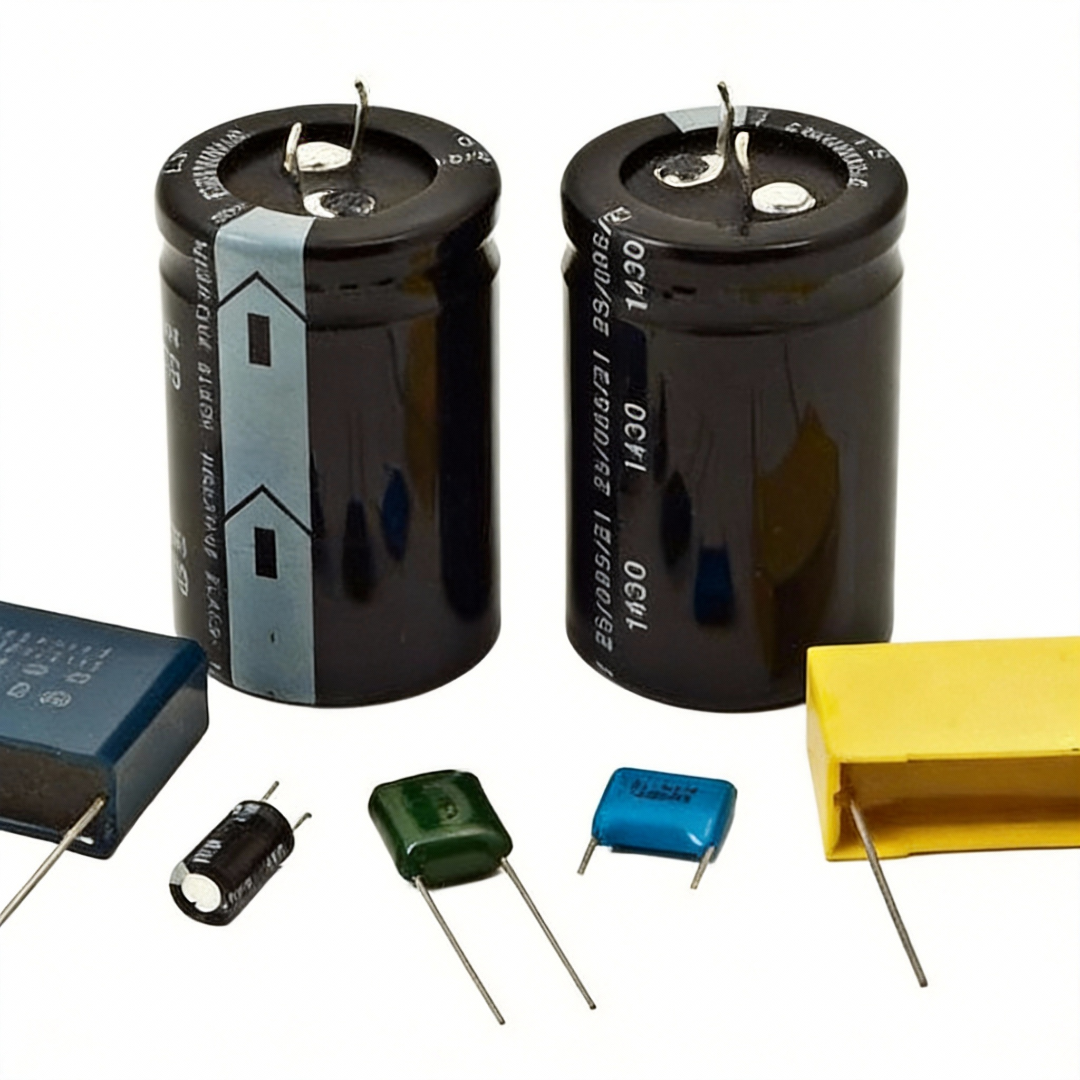
A switch-mode converter typically relies on four main electronic components:
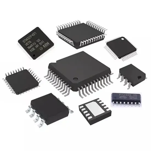
The LM3671 is a step-down DC-DC converter IC designed for high efficiency. Designing a switching regulator like this is generally more complex than a linear regulator due to the requirement of external inductors and filter capacitors.
The LM317 is a classic 3-terminal positive adjustable voltage regulator. Unlike switching regulators, it dissipates excess power as heat but is much simpler to use.
!LM317 Pinout Diagram
The calculator helps design DIY switching circuits by calculating critical parameters like Duty Cycle/inductor values/diode power/current limits. It supports input variables like Vin/Vout/switching frequency to generate output values for custom regulator designs.
It covers Buck/Boost/Inverter regulator designs. For example/you can calculate step-down (Buck) circuits (e.g./12V to 5V) or step-up (Boost) configurations using components like MOSFETs/inductors/diodes.
Use the default values provided: 0.01 ohms for the current sense resistor and 10 Kohms for the top feedback resistor (Rf1). These are safe starting points for most designs.
It uses input parameters like Vin(max)/Vout/ripple/current limits to compute optimal L and C values. For example/higher switching frequencies reduce inductor size/while ripple requirements affect capacitor selection.
Yes! While focused on switching regulators (e.g./LM25085)/the calculator also supports linear regulator components like LM317. Input your target voltage/current/resistor values to generate R1/R2/output voltage results.
ICAllIn’s Resistor Color Code Calculator is an interactive tool for identifying resistor values based on 4-band, 5-band, and 6-band color codes. Simply select the colors, and the calculator will display the resistance in Ohms (Ω), tolerance, and power rating. Whether you are building a circuit, repairing electronics, or sorting resistors in your lab, this calculator provides an accurate and efficient way to decode resistor values.
ICAllIn’s Ohm’s Law Calculator helps engineers and students quickly calculate resistance, current, voltage, and power in an electrical circuit. Simply enter any two known values, and the calculator will instantly compute the remaining parameters. This fast and easy-to-use online tool illustrates the fundamental relationship between voltage, current, and resistance, making it essential for circuit design, troubleshooting, and electronics learning.
The Op Amp Voltage and Gain Calculator is an easy-to-use tool for analyzing operational amplifier circuits. It calculates the output voltage, inverting gain, and non-inverting gain based on the input parameters. Simply enter the values of V1, V2, Vp, Vn, and the resistor values R1, R2, R3, and R4, and the calculator will instantly provide accurate results. This tool is suitable for both professional engineers and beginners learning op amp circuit design.