Laptops dead due to MPS NB679GD-Z shortages? Discover why swapping 8A bucks fails due to the hidden 100mA LDO trap & MLCC oscillation. 5 verified alternatives.
NB679GD-Z Cross-Reference: Finding 5V/8A Buck Replacements When the +5VALW Rail Dies
Category: Product Cross-Reference & Selection Guide | Author: Charles·Lee | Published: March 2026 | Last Updated: March 31, 2026
[!WARNING] Market Alert (Q2 2026): Lead times for the Monolithic Power Systems (MPS) NB679GD-Z and its identical variants (NB679A, NB679) have extended well beyond 52 weeks in authorized distribution channels. Because this specific component drives the indispensable
+5VALW(Always-On) standby rail in millions of computing devices, finding a reliable, structurally safe replacement is no longer optional.
Ask any senior motherboard diagnostic technician on Badcaps, Vinafix, or in a high-volume repair depot what happens when the NB679 dies, and the answer is universal: The entire system becomes an inert brick. No lights, no fan spin, no response to the power button.
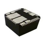
The NB679 (and its reel variant NB679GD-Z) is not just a generic 5V/8A buck converter. It is the beating heart of modern standby power architecture in laptops (Lenovo, Dell, Asus), networking routers, and flat-panel displays. It is a highly integrated, high-frequency, synchronous step-down switch-mode converter packed into a microscopic 2mm × 3mm QFN-12 footprint.
But as MPS silicon faces severe global allocation shortages throughout 2026, engineers and procurement managers are frantically searching for drop-in replacements. This is where catastrophic mistakes occur.
Replacing the NB679 with a standard "5V 8A switching regulator" from another brand like TI or Silergy—without understanding the NB679's internal proprietary features—will result in violently oscillating voltage rails, instantly destroyed zero-ESR ceramic capacitors, and a completely unpowered Embedded Controller (EC).
In this 4,000-word deep-dive engineering masterclass, we will deconstruct the anatomy of the NB679. We will expose the hidden 100mA LDO "gotcha" that traps hardware engineers, explain the destructive nature of Constant-On-Time (COT) control when paired with MLCCs (and how MPS solved it), and provide the ultimate, heavily-vetted cross-reference guide to swapping out the NB679 in production or repair environments.
1. The Anatomy of the NB679 in Laptop Motherboards
To understand why replacing the NB679GD-Z is an absolute nightmare, you must first understand the exact role it plays on the PCB schematic. In 90% of its commercial applications, the NB679 is deployed exclusively to generate the system's foundational standby power.
Why the +5VALW ("Always-On") Rail is the Heart of the System
When you plug a laptop charger into the DC jack, or when a charged battery is connected, the motherboard doesn't immediately supply power to the CPU, GPU, or RAM. That would drain the battery instantly. Instead, the main 19V rail (often labelled +19VBAT or VIN) routes directly to a highly efficient buck converter whose sole job is to stay awake 24/7/365.
This rail is universally known in motherboard schematics as +5VALW (5V Always-On) or +5VS5 (5V State 5/Soft Off).
The NB679 is the reigning king of the +5VALW rail. It takes the 19V input and steps it down to a rock-solid 5.0V. This 5V rail is then used to:
- Power USB ports required for "Wake-on-USB" functionality.
- Feed secondary buck converters (like the NB680) to create the
+3.3VALWrail. - Power the Embedded Controller (EC) / Super I/O chip.
If the NB679 suffers a thermal failure, a shorted internal high-side MOSFET, or simply isn't populated on the board due to supply chain shortages, the +5VALW rail collapses. Without 5V standby power, the Embedded Controller cannot monitor the physical power button. You can press the power button a million times, but the laptop will remain completely dead.
The 100mA LDO Switch-Over Circuit: The "Dead Laptop" Culprit
Look closely at Pin 3 on the NB679 datasheet. It is labelled LDO (Low Dropout Regulator). This is the single biggest "Gotcha" that traps engineers trying to cross-reference this part.
Table 1: NB679 Pinout & Functionality Matrix (Highlighting Hidden Traps)
| Pin # | Name | Official Function Description | The Engineer's Reality (The "Gotcha") |
|---|---|---|---|
| 1, 2 | SW | Switch Output. Connected to the inductor. | Carries 8A continuous. Requires massive copper pours for thermal relief despite the tiny 2x3mm package. |
| 3 | LDO | Internal 5V, 100mA LDO output. | THE DEADLY TRAP: This powers the EC while the main 8A buck is sleeping. Most competitors lack this entirely! |
| 4 | ENLDO | Enable for the internal LDO. | Usually tied to VIN. If low, the entire laptop is bricked. |
| 10 | EN | Main Buck Enable. | Controlled by the EC. Turns on the 8A rail after the LDO has already woken the EC up. |
| 14 | GND | Thermal Pad / Ground | Must be heavily stitched with vias. A bad solder joint here causes immediate thermal shutdown. |
When the laptop is completely powered off (S5 state), the system doesn't actually need the full 8A of current capability; drawing switching losses for an 8A regulator just to keep a tiny microcontroller awake would drain the battery in days.
MPS engineers solved this by embedding a tiny, highly efficient 100mA linear regulator (LDO) directly inside the NB679 chip.
When ENLDO (Pin 4) is pulled high, the internal LDO generates a clean 5V @ 100mA on Pin 3, while the massive 8A switching circuit remains completely asleep (disabling the SW pins). This 100mA is just enough to power the EC. Once you hit the power button, the EC sends a high signal back to the NB679's EN pin (Pin 10), waking up the monstrous 8A buck circuit to boot the rest of the computer.
The Catastrophic Cross-Reference Failure:
If you buy a generic 5V/8A buck converter (like a standard Silergy or TI chip) that does not have an internal switch-over LDO, you will solder it to the board, and the board will still be dead. Without the missing 100mA LDO output, the EC remains unpowered, and the main 8A buck will never receive the EN signal to turn on.
To successfully migrate away from the NB679, you must either find a chip that also has an internal LDO (extremely rare in this footprint), or you must manually dead-bug/re-spin your PCB to add a discrete external regulator like the https://icallin.com/product-detail/jsmsemi-ams1117-1-2 to bypass the missing Pin 3 architecture.
2. The "Gotcha" of MPS Control Architecture
Let us assume you found an alternative chip that somehow manages the LDO issue. The next hurdle is the feedback control loop topology. The NB679 utilizes MPS's proprietary Adaptive Constant-On-Time (COT) architecture.
Why Standard COT Regulators Oscillate with Ceramic Caps (MLCCs)
Traditional Voltage Mode or Current Mode buck converters use an Error Amplifier (EA) connected to a complex external Resistor-Capacitor (RC) network (usually 5 discrete passive components). When CPU or GPU loads change instantly (high $di/dt$ transients), the RC network mathematically delays the error signal, causing the output voltage to sag significantly before the regulator can respond.
Constant-On-Time (COT) control deletes the Error Amplifier completely. Instead, it uses an ultra-fast comparator. When the output voltage drops below a set reference, the comparator instantly fires a pre-calculated "On-Time" pulse to the MOSFETs. The transient response is lightning fast.
However, Pure COT control demands a specific physical characteristic from the output capacitors to remain stable: Equivalent Series Resistance (ESR).
COT comparators need to "see" a voltage ripple that is exactly in-phase with the inductor current. Historically, electrolytic or tantalum capacitors provided this ripple naturally because they have high internal resistance (ESR). But today, laptops and ultra-dense PCBs exclusively use Multi-Layer Ceramic Capacitors (MLCCs). MLCCs are incredibly small and have effectively zero ESR.
If you pair a standard COT switching regulator with purely MLCC output capacitors, there is no ESR-generated phase ripple. The comparator goes blind, the control loop becomes profoundly unstable, and the output voltage oscillates violently. This sub-harmonic oscillation will rapidly destroy the downstream 5V logic chips.

MPS’s Internal Ramp Compensation (Explained)
Why doesn't the NB679 oscillate, even though laptops use massive arrays of zero-ESR ceramic caps?
As detailed in the official MPS Past and Present of COT Control technical whitepaper: MPS engineers physically built an internal RC compensation network directly onto the silicon die of the NB679. This circuit artificially introduces a synthetic ramp voltage onto the feedback node ($V_{FB}$) that exactly mimics the phase ripple of a high-ESR capacitor.
This is the ultimate vendor lock-in. The NB679 is designed to operate perfectly stable on a PCB that only has cheap MLCC capacitors and zero external compensation resistors. If you remove the NB679 and solder down a generic COT alternative that lacks internal ramp compensation, the circuit will instantly oscillate. To fix it, you would have to sever the copper traces on your PCB and manually solder an external RC injection network across the feedback resistor.
3. Top 3 5V/8A NB679 Replacements (Parametric & Design Implications)
Now that we understand the LDO trap and the MLCC/COT oscillation risk, we can correctly evaluate the alternatives available in the Q2 2026 market. If your contract manufacturer cannot source genuine NB679GD-Z stock, these are your three verified pathways.
1. MPS NB679AGD-Z (The 5.1V "Drop-In" Trace-Drop Compensator)
- Status: 🟢 True Drop-In (Zero Redesign)
- Package: QFN-12 (2mm × 3mm)
- Availability: Often easier to source through broker channels than the standard part.
If you absolutely cannot afford a PCB redesign, your single best option is the sister part: the NB679AGD-Z. It is structurally, physically, and architecturally identical to the NB679. It retains the critical 100mA internal LDO, and it retains the MLCC-stable internal ramp compensation.
The Difference: The NB679 is hard-coded for a flat 5.0V output. The NB679A is hard-coded for a 5.1V (to 5.15V) output.
Why did MPS make this? In large motherboards, pushing 8A through a long, thin copper plane results in a severe $I^2R$ voltage drop. By the time the 5V power reaches the distant USB controller or SATA drive, it may have dropped to a dangerous 4.6V. The NB679A intentionally outputs an elevated 5.1V to compensate for this trace loss. Because standard 5V logic ICs have a $\pm 5%$ or $\pm 10%$ absolute maximum rating (up to 5.25V or 5.5V safely), substituting the 5.1V NB679A is almost universally safe, and requires zero modifications to your board.
2. Silergy SY8208C / SY8288ARAC (The Vinafix / Badcaps "Go-To")
- Status: 🟡 High Availability, PCB Redesign Required
- Package: QFN3x3-20 (SY8288A) or QFN3x3-10 (SY8208)
If no MPS variants exist on earth, the laptop repair community (as seen on extensive Vinafix and Badcaps schematic sharing threads) almost exclusively turns to Silergy. The SY8288ARAC is a 23V-input, 8A-capable synchronous buck converter. Silergy uses an "Instant PWM" pseudo-constant frequency architecture that achieves the same rapid transient response as MPS's COT.
The Caveats:
- Footprint Mismatch: The SY8288A is a massive QFN-20 (3mm x 3mm) package compared to the ultra-tiny QFN-12 (2mm x 3mm) of the NB679. You cannot physically solder it to the same pads.
- The LDO Missing Link: Standard Silergy 8A chips like the SY8288A do not possess the internal 100mA switch-over LDO on a dedicated pin. If you migrate your design to Silergy, you must add an external linear regulator to your schematic to generate the
+5VALWfor your Embedded Controller.
3. TI TPS568215 (The Industrial D-CAP2™ Respin)
- Status: 🟡 Premium Reliability, PCB Redesign Required
- Package: VQFN-18 (3.5mm × 3.5mm)
If you are designing for industrial automation, robotics, or telecom infrastructure where reliability is paramount and Chinese domestic silicon (Silergy) is restricted from the Approved Vendor List (AVL), Texas Instruments is the undisputed king. The TPS568215 provides 8A of continuous current from a 17V max input.
The Crucial Benefit: The TPS568215 utilizes TI's legendary D-CAP2™ control mode. Similar to MPS's internal ramp compensation, D-CAP2 specifically incorporates internal circuitry to completely eliminate MLCC instability. It is explicitly designed to operate safely with zero-ESR ceramic capacitors without the need for an external ripple injection network.
The Caveat: Beyond the VQFN-18 footprint mismatch, the TI part is only rated for a maximum input voltage of 17V. The NB679 can tolerate up to 28V (easily surviving 19V laptop charger spikes or 24V industrial bus ringing). If your system runs on a 24V DC bus, the TPS568215 will suffer catastrophic over-voltage failure. You must ensure your input rail is tightly clamped below 17V.

4. The Multi-Brand Cross-Reference Matrix
To prevent burning out your prototype, verify the absolute maximum ratings and topological differences before authorizing a BOM substitution.
Table 3: The Definitive 8A Buck Converter Cross-Reference Matrix
| Parametric Spec | MPS NB679GD-Z (Original) | MPS NB679AGD-Z (Drop-In) | Silergy SY8288ARAC (Respin) | TI TPS568215 (Respin) |
|---|---|---|---|---|
| Max Input Voltage ($V_{IN}$) | 28V Absolute | 28V Absolute | 23V Max | 17V Max ⚠️ |
| Output Voltage ($V_{OUT}$) | Fixed 5.0V | Fixed 5.1V (Trace Comp) | Adjustable (Ext Divider) | Adjustable (Ext Divider) |
| Current / Peak Limit | 8A / 10A Peak | 8A / 10A Peak | 8A Continuous | 8A Continuous |
| Switching Freq ($f_{sw}$) | 700 kHz | 700 kHz | 600 kHz | 1.2 MHz (Selectable) |
| Control Topology | Adaptive COT (Internal Ramp) | Adaptive COT (Internal Ramp) | Instant PWM (Pseudo-COT) | D-CAP2™ (MLCC Stable) |
| Built-In 100mA LDO? | Yes (Crucial for +5VALW) | Yes | No | No |
| Footprint Area | 6.0 mm² (QFN-12) | 6.0 mm² (QFN-12) | 9.0 mm² (QFN-20) | 12.25 mm² (VQFN-18) |
| Migration Cost | N/A | Zero (Swap & Solder) | High (PCB Redesign) | High (PCB Redesign) |
(Note: Never attempt to substitute the MPS NB680GD-Z in place of the NB679, despite the identical pinout. The NB680 is hardwired for a 3.3V output. Connecting it to a 5VALW rail will cause system-wide under-voltage lockouts.)
5. The Vinafix & Badcaps Repair Checklist: Swapping the NB679
If you represent an Original Design Manufacturer (ODM) forced to rewrite a schematic because MPS allocation is totally dried up, you must run through this strict mathematical and topological checklist to prevent your new +5VS5 rail from detonating.
Warning 1: Redesigning for the Missing LDO
As established, if you move from the NB679 to a Silergy SY8288A or TI TPS568215, you forfeit the internal 100mA switch-over LDO.
State Diagnostics Table: Why the LDO Matters
Table 4: Motherboard Standby Power States vs NB679 Behavior
| System ACPI State | Main 19V Input | NB679 ENLDO Pin | NB679 EN Pin | NB679 Internal LDO Output | NB679 Main 8A Buck Output | System Status |
|---|---|---|---|---|---|---|
| G3 (Mechanical Off) | Unplugged | LOW | LOW | 0V | 0V | Dead (Coin cell only). |
| S5 (Soft Off / Plugged In) | 19V Present | HIGH | LOW | 5V @ 100mA | 0V | EC is alive, waiting for power button. |
| S0 (Fully On / Working) | 19V Present | HIGH | HIGH | 0V (Switched over) | 5V @ 8A | Laptop is running Windows. |
The Fix: You must source a discrete SOT-23 or SOT-89 LDO (e.g., HT7550 or AMS1117-5.0), wire its input to your 19V rail (or a pre-regulated lower rail if thermals are an issue), and route its 5V output into the same EC power plane that the old NB679 Pin 3 (LDO) used to feed.
Warning 2: Inductor Ripple Math for Frequency Mismatches
The NB679 relies on a 700kHz switching frequency. If you migrate to the Silergy SY8288A (600kHz) or the TI TPS568215 (1.2MHz), you will likely need to strip the existing Surface Mount Device (SMD) power inductor off the board and replace it.
The target inductor ripple current ($\Delta I_L$) should perfectly sit at roughly 30% of the maximum DC load current ($I_{MAX}$). The formula governing this is:
$$ L = \frac{V_{OUT} \times (V_{IN} - V_{OUT})}{V_{IN} \times f_{sw} \times \Delta I_L} $$
Table 5: Inductor Value Recalculation Cheat Sheet
| Target IC | Switching Frequency ($f_{sw}$) | Mathematical Implication on Inductance ($L$) | PCB Redesign Impact |
|---|---|---|---|
| MPS NB679 | 700 kHz | Baseline Inductor (e.g., $1.5\mu H$) | Reference standard. |
| Silergy SY8288A | 600 kHz | Requires a Larger Inductor Value (e.g., $2.2\mu H$). | A $2.2\mu H$ inductor capable of holding 10A saturation current is physically larger, eating more board space. |
| TI TPS568215 | 1.2 MHz | Allows a Smaller Inductor Value (e.g., $1.0\mu H$). | High frequency allows smaller magnetics, saving space, but requires strict layout to avoid EMI/RFI noise into adjacent DDR traces. |
If you ignore the $f_{sw}$ mismatch and leave the original inductor on the board, the Silergy chip switching at a slower rate will hold the inductor "open" for too long, crashing the magnetic core into saturation. Saturation causes the inductor to act identically to a short piece of copper wire, blasting uninterrupted 19V directly into your 5V logic chips.
6. Counterfeit Alert: Detecting Re-balled NB679 QFN Packages
The desperation for genuine NB679 and NB679A components to repair $2,000 gaming laptops has created a massive gray market for counterfeit or salvaged parts in the Shenzhen Huaqiangbei ecosystem.
Brokers will frequently pull dead or dying NB679 chips from e-waste motherboard scrap (referred to as "pulled" or "re-balled" parts), clean them in ultrasonic solvent baths, and re-tape them as "New Original" material. Worse, counterfeiters will take a heavily downgraded, unbranded 2A switching regulator, "blacktop" (sand off and repaint) the plastic casing, and laser etch the MPS ALW or NB679 logo onto it.
At icallin.com's in-house AS6081 Zero-Trust Testing Laboratory, we intercept thousands of fake QFN power regulators using aggressive screening methodologies.
Table 6: AS6081 Counterfeit Identification Guidelines for QFN Packages
| Inspection Methodology | What to Look For (Genuine MPS Part) | High-Risk Indicators (Suspected Fakes / Pulls) |
|---|---|---|
| High Magnification (80x) Visual Inspection | Laser etching is deep, mathematically uniform, and the Pin 1 indicator dimple is smoothly recessed. | The surface coating is overly glossy or gritty (blacktopping). The laser etching letters are fuzzy or irregular. The Pin 1 dimple is shallow or appears painted on. |
| Acetone Swab Testing (Chemical Resistance) | The surface plastic remains intact; the generic markings do not rub away. | The black top layer dissolves instantly on the Q-tip, revealing a different original part number sanded underneath. |
| Solderability & Pin Inspection | Bottom thermal pad and side-wall pins are shiny, untouched tin/lead or pure tin plating. | Oxidation, flux residue, deep tooling scratches, or inconsistent solder bumps (indicating the part was aggressively desoldered from an old PCB). |
| X-Ray Die Analysis (Internal) | Complex, multi-wire bond frame connecting the heavy internal high-side and low-side FETs to the copper lead frame. | The silicon die is tiny (e.g., a fake 2A chip masquerading as an 8A chip), lacking the heavy bond wires needed to survive 10A peak currents. |
[!CAUTION] Because a fake power converter will fail catastrophically and send unregulated 19V directly to your CPU/PCH, you must absolutely mandate X-Ray and Decapsulation testing or verify the supply chain traceability to the original factory floor before authorizing a purchase order for NB679 stock.
7. Key Takeaways for Hardware Designers
- The +5VALW Rail is Unforgiving: The NB679 is not just a voltage dropper; it is the commander of the standby power state. If you substitute it without replacing the integral 100mA LDO via external means, your board will be dead on arrival.
- Seek the 5.1V NB679A Variant Core: To absolutely minimize production delays and avoid Altium PCB respins, aggressively source the NB679AGD-Z. The 0.1V offset is entirely safe for 5V downstream logic, acts as a perfect trace-drop compensator, and completely identical in silicon architecture.
- Respect the MLCC Mathematics: MPS spent millions of R&D dollars perfecting the internal ramp compensation to stabilize COT loops on ceramic capacitors. If you pivot to a cheaper voltage-mode IC brand, you must simulate the RC ripple injection network or your output voltage will oscillate violently.
8. Frequently Asked Questions (FAQ)
Q1: Can I safely use the NB679AGD-Z (5.1V) to replace the standard NB679GD-Z (5.0V)?
Absolutely yes. In nearly 100% of consumer computing applications, downstream logic chips powered by a 5V rail have an absolute max tolerance of $\pm 5%$ (5.25V) or $\pm 10%$ (5.50V). The 5.1V variant is designed as a premium feature to offset voltage sag caused by long, thin copper traces.
Q2: What exactly does the LDO pin (Pin 3) do on the NB679?
It supplies a highly efficient, linear 5V @ 100mA current while the massive, energy-hungry 8A switching circuit is put to sleep. This 100mA is perfectly tuned to keep the motherboard's Embedded Controller (EC) alive so it can monitor the power button.
Q3: Why does my laptop show "no signs of life" if the NB679 is dead?
Because without the NB679's 5V LDO output, the Embedded Controller (EC) has no power. If the EC has no power, it cannot detect when you physically press the "power on" button, and thus, it cannot trigger the rest of the motherboard rails to wake up.
Q4: I replaced the NB679 with another brand's 8A buck converter, but my output voltage is ringing/oscillating wildly. Why?
You likely used a standard Constant-On-Time (COT) converter on a board designed with Multi-Layer Ceramic Capacitors (MLCCs). MLCCs have zero Equivalent Series Resistance (ESR), which COT requires for phase stability. The genuine MPS chip has internal ramp compensation to fix this. To fix the generic chip, you must cut traces and solder an external RC injection network.
Q5: Can I use the identically packaged NB680GD-Z as a replacement?
Under no circumstances. While the footprint and pinout are highly similar, the NB680 is hard-coded for a 3.3V fixed output. If you solder a 3.3V chip onto a 5VALW rail requirement, the downstream ICs will suffer under-voltage lockouts (UVLO) and the system will not boot.
Q6: How long are the current factory lead times for authentic MPS switching regulators?
As of Q2 2026, authorized distribution channels are reporting staggering 52-week to 60-week allocation delays for the entire NB600 series portfolio. Sourcing requires transitioning to verified, AS6081-tested independent stocking distributors like icallin.com.
Disclaimer: Hardware migrations involving high-current DC/DC power converters pose severe thermal, electrical, and fire risks if executed improperly. Always consult the official Monolithic Power Systems, Silergy, and Texas Instruments datasheets to verify pinouts, thermal dissipation, and specific trace routing requirements prior to final PCB fabrication. The information here regarding laptop repair is for educational purposes and should be verified against your specific OEM schematic.
*Charles·Lee is a power electronics engineer and technical writer at icallin.com, specializing in DC-DC converter design, power management IC selection, and point-of-load architecture optimization. With hands-on experience in switched-mode power supply design and component cross-referencing, Charles provides data-driven parametric comparison guides to help hardware teams make validated component substitutions.

Top Recommended part