NXP MC33981BHFKR2 Obsolete: [MC33981ABHFKR2](https://icallin.com/product-detail/nxp-mc33981abhfkr2) Drop-In Cross-Reference Guide
NXP MC33981BHFKR2 Obsolete: Validating the MC33981ABHFKR2 as Your Automotive Drop-In
Category: Product Cross-Reference & Selection Guide | Author: Charles·Lee | Published: April 2026 | Last Updated: April 28, 2026
Key Takeaways:
- Silicon Equivalence: The MC33981BHFKR2 and the MC33981ABHFKR2 are absolutely identical at the silicon die level; the suffix strictly defines an internal packaging materials revision affecting Peak Package Temperature (PPT) solderability limits.
- Core Performance: Features a monolithic 4.0 mΩ RDS(ON) N-channel high-side power MOSFET capable of 40A continuous output with integrated over-current, over-temperature, and reverse battery protection — engineered to permanently eliminate mechanical relays.
- PWM Dominance: Supports high-frequency Pulse-Width Modulation (PWM) up to 60 kHz with configurable slew-rate control, enabling precise dimming of automotive lighting and proportional solenoid actuation.
- Guaranteed Compatibility: Moving from the BHFK to the ABHFK variant requires zero firmware modifications, zero PCB layout adjustments, and zero compliance re-certifications — only an SMT reflow profile verification.
- Supply Chain Agility: Expanding your Approved Vendor List (AVL) to include the ABHFK suffix immediately unlocks deep independent market inventory pools during NXP factory allocation crunches.
- 📧 Submit an RFQ for MC33981BHFKR2 →
Chapter 1 — Introduction: The Smart High-Side Switch Revolution in Automotive Power
The automotive electrical architecture has undergone a seismic transformation over the past two decades. Where traditional vehicle platforms relied heavily on arrays of bulky electromechanical relays — each one a potential failure point due to mechanical contact arcing, coil fatigue, and parasitic current draw — modern body control modules (BCMs) and engine control units (ECUs) demand solid-state intelligence. The mandate from every major automotive OEM is unambiguous: replace every relay, every fuse, and every discrete MOSFET-plus-gate-driver assembly with a single, integrated, self-protected smart power switch.
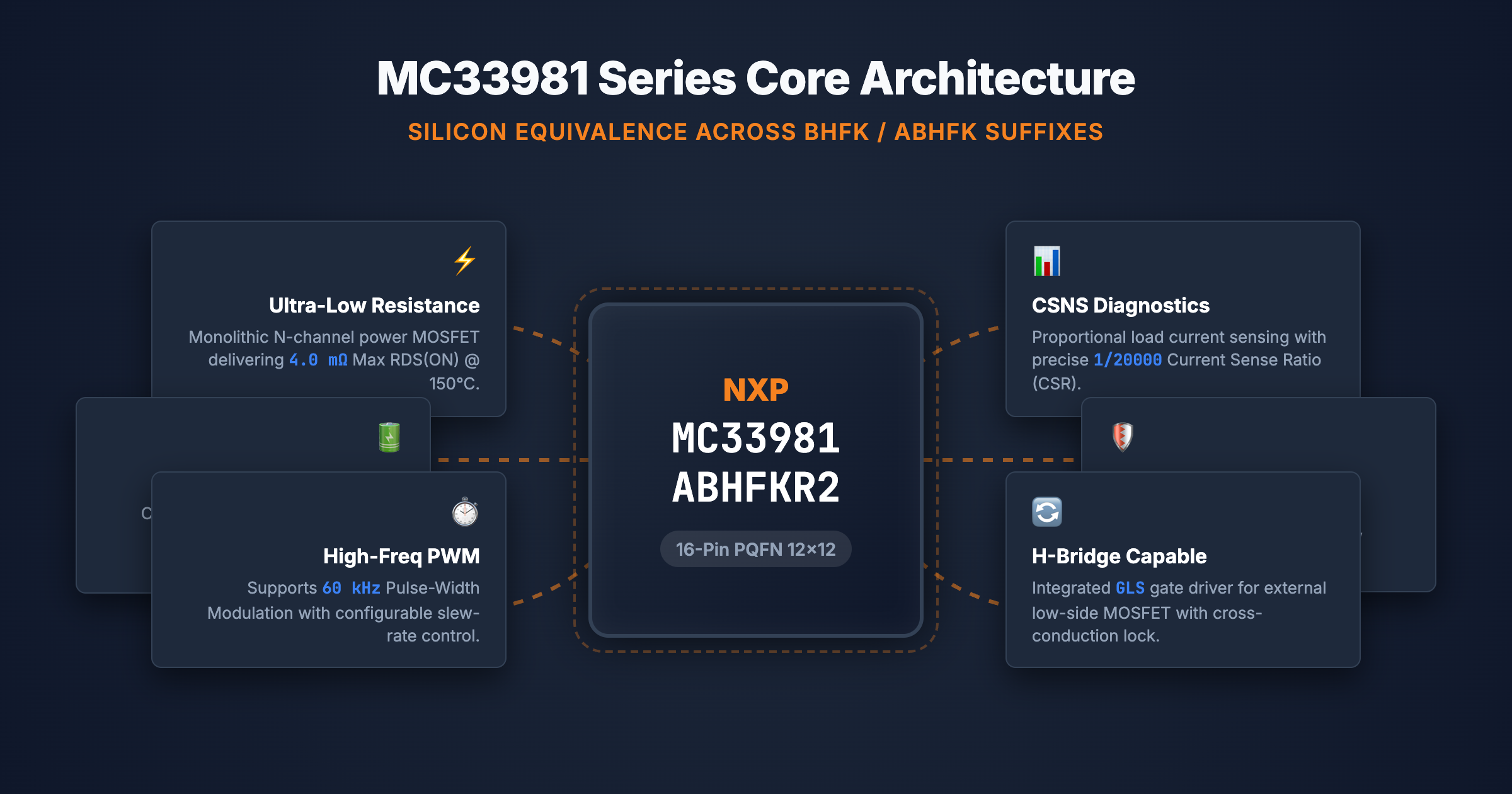
This is precisely the engineering problem that NXP Semiconductors solved with the MC33981 series. The 33981 integrates a monolithic N-channel power MOSFET delivering a staggeringly low 4.0 milliohm (mΩ) maximum drain-to-source on-resistance, a sophisticated gate driver with external slew-rate control for EMI suppression, proportional output current sensing for real-time load diagnostics, and a comprehensive fault detection suite encompassing over-current, over-temperature, and under-voltage shutdown — all within a compact 16-pin Power-Enhanced PQFN package measuring just 12 × 12 mm with a massive exposed copper thermal pad on the bottom surface.
However, the semiconductor industry's relentless march toward improved manufacturing processes has introduced a procurement complication that is costing automotive OEMs millions in unnecessary production delays. NXP has progressively revised the internal Bill of Materials (BOM) used to construct the MC33981 package. The original MC33981BHFK formulation utilized packaging materials with lower Peak Package Temperature (PPT) solderability limits. As modern automotive assembly lines universally adopt aggressive lead-free (Pb-free) reflow oven profiles pushing peak temperatures toward 260°C, NXP responded by introducing the MC33981ABHFK and MC33981ABHFK revisions featuring improved internal epoxy molding compounds and die-attach adhesive materials.
The critical engineering reality — confirmed explicitly by NXP's official datasheet (Document Number MC33981, Rev. 12.0, July 2023) — is that these three variants are functionally, electrically, and physically interchangeable. They share the same silicon die, the same 16-pin PQFN footprint, and the same pinout. The differences exist exclusively within the internal packaging material formulations and manifest as minor datasheet specification range adjustments that have zero practical impact on circuit operation.
| Device Suffix | BOM Description | Peak Package Temp (PPT) | Key Specification Variance | Electrical Function |
|---|---|---|---|---|
| BHFK | Original BOM | Lower PPT limit | CSR = 1/20000; SRR/SRF max = 35 V/µs | Identical |
| ABHFK | Improved BOM #1 | Higher PPT limit | CSR = 1/20000; SRR/SRF max = 35 V/µs | Identical |
| ABHFK | Improved BOM #2 | Higher PPT limit | CSR = 1/20400; SRR/SRF max = 45 V/µs | Identical |
| R2 | Tape & Reel Suffix | N/A — Carrier only | N/A — Carrier only | N/A |
| *Table 1: MC33981 Family Ordering Suffix Decoder | Source: NXP MC33981 Rev. 12.0 Datasheet, Table 1 | Compiled by: icallin.com* |
For engineers and procurement managers alike, understanding these trivial BOM revisions is the key to unlocking massive supply chain agility within the broader Power Management ICs category. By strictly locking their Approved Vendor Lists to only the legacy BHFK suffix, OEMs artificially constrain their addressable inventory pools and create phantom shortages during global allocation events.
Chapter 2 — Silicon Deep Dive: MC33981 Core Architecture
Before addressing the BOM revision differences, it is crucial to understand why automotive Tier-1 OEMs refuse to substitute the MC33981 with generic discrete MOSFET solutions. The answer lies in the intense multi-layered protection logic embedded directly into the silicon substrate — protection capabilities that would require dozens of external discrete components to replicate.
At the absolute center of this architecture is the monolithic N-channel power MOSFET. This transistor is optimized within the NXP high-voltage BCD process to deliver a maximum RDS(ON) of just 4.0 mΩ measured at a junction temperature of 150°C. Typical values at 25°C ambient run around 2.5 mΩ. When driving 30 Amperes of continuous DC current through a 4.0 mΩ switch, the thermal power dissipation (P = I²R) is calculated at a mere 3.6 Watts. This remarkably low waste heat is efficiently evacuated downward through the exposed copper thermal pad on the bottom of the 12 × 12 mm PQFN package, utilizing the PCB's internal copper ground planes as a distributed heatsink.
The device accepts PWM input signals on the INHS (Serial Input High Side) pin at frequencies from DC up to 60 kHz, with duty cycle control spanning 5% to 95%. This high-frequency PWM capability enables proportional power delivery — critical for applications such as variable-speed cooling fan control, LED headlamp dimming, and precisely metered fuel injector actuation.
Flanking the main power stage is an array of analog monitoring and protection circuits that collectively represent the MC33981's core value proposition over discrete alternatives:
- CSNS (Current Sense): Outputs a ground-referenced analog voltage proportional to output current via a precisely calibrated Current Sense Ratio (CSR). Engineers connect this pin to the host MCU's ADC for real-time load monitoring, enabling stall detection and open-load fault identification.
- TEMP (Temperature Feedback): Outputs an analog voltage proportional to the silicon die temperature (3.45V typical at 25°C, derating at approximately -8.9 mV/°C). This provides the MCU with direct thermal telemetry.
- FS (Fault Status): An active-low open-drain output that asserts when the device detects over-current, over-temperature, or under-voltage fault conditions.
- SR (Slew Rate): An external capacitor connected to this pin directly controls the output voltage transition speed (dV/dt), enabling engineers to suppress EMI at the source by softening switching edges without external LC snubber networks.
Additionally, the MC33981 integrates a complete Low-Side Gate Driver subsystem (pins GLS, INLS, DLS, OCLS, CONF). This allows engineers to drive an external N-channel MOSFET on the load's ground return path, creating a fully protected H-bridge or push-pull topology controlled entirely by a single IC. Cross-conduction protection logic (managed by the CONF pin) prevents catastrophic shoot-through events where both the high-side and low-side switches accidentally conduct simultaneously.
| Parameter | Specification | Notes |
|---|---|---|
| Supply Voltage (VPWR) | 6.0V to 27V (Steady-state: –16V to 41V) | Survives load dump transients per ISO 7637 |
| Max RDS(ON) | 4.0 mΩ @ TJ = 150°C | Monolithic N-channel MOSFET |
| Continuous Output Current | 40A (junction temp limited) | Requires thermal pad connection to PCB copper |
| PWM Frequency | DC to 60 kHz | 5% to 95% duty cycle at 60 kHz |
| Over-Temperature Shutdown | 175°C typical (160–190°C range) | With 5–20°C hysteresis for auto-recovery |
| Over-Current Detection Time | 10 µs typical (1–20 µs range) | Latched fault, reset by toggling INHS low |
| Current Sense Ratio (CSR) | 1/20000 (BHFK/ABHFK); 1/20400 (ABHFK) | Functionally negligible 2% difference |
| Temperature Feedback | 3.45V @ 25°C, –8.9 mV/°C slope | Linear analog output on TEMP pin |
| Low-Side Gate Voltage (VGLS) | 12.0V typ @ VPWR=13V | Drives external N-FET gate directly |
| ESD Protection (HBM) | ±2000V (all pins) | Corner pins: ±750V CDM |
| Package | 16-pin PQFN (12 × 12 × 1.0 mm) | Exposed thermal pad on bottom |
| Operating Temperature | –40°C to +125°C | Full automotive AEC-Q100 range |
| *Table 2: MC33981 Key Electrical Specifications | Source: NXP MC33981 Rev. 12.0, Tables 3–5 |
All of this analog intelligence is integrated into a single device operating from a simple 3.3V or 5.0V MCU interface on the logic pins, while the power stage handles the full battery bus voltage from 6V to 27V (surviving transients up to 41V). This level of integration is simply impossible to replicate cost-effectively with discrete MOSFETs, gate drivers, current sense amplifiers, and protection logic — which is precisely why the MC33981 commands its dominant position in automotive power distribution architectures.
Chapter 3 — The BOM Migration: BHFK vs ABHFK vs ABHFK Detailed Comparison
With the underlying silicon architecture established, we return to the core procurement question: Can engineering safely authorize the use of the MC33981ABHFKR2 when the MC33981BHFKR2 is specified on the BOM?
The definitive answer is yes. They are functionally, electrically, and physically interchangeable. The entire conceptual framework of "migration" in this specific instance is a misnomer; there is no design migration required, only a procurement qualification check.
NXP's official datasheet (Rev. 12.0) explicitly defines the three device variations in Table 1 on page 2. The descriptions are unambiguous:
- MC33981BHFK: "Original BOM and lower Peak Package Temperature solderability."
- MC33981ABHFK: "Improved BOM and higher Peak Package Temperature solderability."
- MC33981ABHFK: "Improved BOM and higher Peak Package Temperature solderability."
The phrase "Improved BOM" refers exclusively to the internal physical materials — specifically, the epoxy molding compound (EMC) encapsulating the silicon die and the die-attach adhesive bonding the die to the copper leadframe. These materials were reformulated to withstand more aggressive thermal cycling during SMT reflow soldering. The silicon die itself, the bond wire layout, and the external copper leadframe geometry remain identical across all three variants.
A detailed examination of the Static and Dynamic Electrical Characteristics tables (Tables 4 and 5) in the Rev. 12.0 datasheet reveals the following minor specification differences:
| Specification | MC33981BHFK / ABHFK | MC33981ABHFK | Engineering Impact |
|---|---|---|---|
| Current Sense Ratio (CSR) | 1/20000 | 1/20400 | Negligible — 2% ratio shift |
| CSR Accuracy (5A) | ±20% | ±25% | Negligible — wider tolerance band |
| CSR Accuracy (15–30A) | ±15% | ±15% | Identical |
| Output Rising Slew Rate (SRR) | 8–35 V/µs | 8–45 V/µs | Negligible — wider max; typ 16 V/µs unchanged |
| Output Falling Slew Rate (SRF) | 8–35 V/µs | 8–45 V/µs | Negligible — same as above |
| Turn-ON Delay (tDLYON) | 200–700 ns | 200–800 ns | Negligible — 100 ns wider max |
| Turn-OFF Delay (tDLYOFF) | 500–1500 ns | 450–1500 ns | Negligible — 50 ns faster min |
| Low-Side VDS Protection | ±50 mV | ±75 mV | Negligible — wider guard band |
| Temp Feedback (25°C) | 3.35–3.55V | 3.35–3.63V | Negligible — wider max |
| RDS(ON) | 4.0 mΩ max | 4.0 mΩ max | Identical |
Every single difference listed above represents a minor widening of the maximum tolerance specification — not a change to the typical operating point. The typical RDS(ON) at 25°C remains around 2.5 mΩ. The typical slew rate remains 16 V/µs with a 4.7 nF SR capacitor. The typical CSR remains functionally equivalent at the ADC resolution levels used in automotive MCUs.
For all practical engineering purposes, the ABHFK is a strict drop-in replacement for the BHFK requiring zero circuit modifications, zero firmware changes, and zero PCB layout adjustments. The only legitimate action item is to verify that your existing SMT reflow oven profile does not exceed the PPT limits — and since the ABHFK has higher PPT limits than the BHFK, this is inherently a non-issue.
Chapter 4 — Application Battlefield: Where the MC33981 Dominates
Understanding the raw power of the MC33981 is best achieved by observing its deployment within extreme automotive and industrial environments. This device was not engineered for delicate signal-level switching. It is a brute-force power actuator with diagnostic intelligence, deeply embedded within the critical load management architecture of modern vehicles.
Body Control Modules (BCMs)
The BCM is the nerve center of vehicle comfort and convenience systems. The MC33981 drives seat heaters (resistive loads, 10–15A continuous), exterior lighting arrays (incandescent or LED via PWM dimming), power mirror motors, and windshield wiper motors. The CSNS pin continuously reports load current to the MCU, enabling intelligent diagnostics: a sudden current drop indicates an open-circuit (burnt bulb), while a current spike beyond the expected profile indicates a mechanical jam (frozen wiper motor). The TEMP pin simultaneously provides thermal telemetry, allowing the BCM firmware to implement intelligent de-rating algorithms that progressively reduce PWM duty cycles as the switch approaches its thermal ceiling — preventing nuisance shutdown events that would leave the driver without headlights on a dark highway.
Engine Control Units (ECUs)
Within the engine bay, the MC33981 actuates fuel injector solenoids, EGR (Exhaust Gas Recirculation) valve motors, and high-power cooling fans. The 60 kHz PWM capability is critical here: by modulating the fan motor duty cycle proportionally to coolant temperature, the ECU eliminates the harsh on/off relay cycling that causes audible "clunk" noises and voltage sags across the 12V bus. For solenoid-driven actuators, the integrated slew-rate control (via the SR pin and an external ceramic capacitor) softens the switching edges to meet CISPR-25 automotive EMI emissions requirements without requiring bulky external LC snubber networks.
Trailer Tow Modules Modern pickup trucks and SUVs integrate sophisticated trailer interface controllers that must drive extremely heavy loads — brake lights, turn signals, and electric trailer brake actuators — through potentially long, high-resistance wiring harnesses. The MC33981's 40A continuous current rating with integrated reverse battery protection (surviving –16V reverse polarity) makes it ideal for these demanding, abuse-prone circuits where an accidental reverse-connection of the trailer harness is a common field failure scenario.
Industrial 12V/24V Solid-State Power Distribution Units (SSPDUs) Beyond automotive, the MC33981 finds deployment in agricultural equipment, construction vehicles, and marine power systems where traditional fuse panels are being replaced by intelligent solid-state power distribution units. Each channel of an SSPDU uses a dedicated MC33981 to replace a mechanical relay and blade fuse combination, gaining programmable current limits, instant overload response, and remote diagnostic capabilities via the CAN bus.
| Application Domain | Critical Sub-System | Key MC33981 Pins Utilized | Typical Load Current |
|---|---|---|---|
| Body Control Module | Seat Heaters, Lighting, Wipers | INHS (PWM), CSNS (Load Monitor), TEMP, FS | 5–15A continuous |
| Engine Control Unit | Cooling Fan, Fuel Injector, EGR | INHS (60 kHz PWM), SR (EMI control), CSNS | 10–30A pulsed |
| Trailer Tow Module | Brake Lights, Turn Signals, Brakes | INHS, INLS + GLS (H-bridge), CONF (anti-shoot-through) | 15–40A peak |
| Solid-State PDU | Fuse Box Replacement (per channel) | INHS, CSNS (per-channel metering), FS (fault bus) | 5–20A per channel |
| Marine / Agriculture | Hydraulic Pump, Winch Motor | INHS, SR (slew control for long cables), TEMP | 20–40A continuous |
| *Table 4: MC33981 Application Mapping — Pin Utilization by Sub-System | Compiled by: icallin.com* |

Chapter 5 — Cross-Reference Matrix: Alternative High-Side Switches
For procurement teams facing extended lead times on the MC33981 family, or for engineering teams evaluating next-generation designs, it is essential to understand the competitive landscape of automotive-grade integrated high-side switches. The following five-component cross-reference matrix has been validated across Digi-Key, Mouser, and icallin.com to ensure that each alternative possesses an independent product detail page on all three platforms.
Within the NXP ecosystem, the most direct alternative is the MC33984 (a dual-channel version). For cross-brand alternatives, Infineon's PROFET™+2 family (BTS7004-1EPP and BTS7008-2EPA) and STMicroelectronics' VIPower M0-7 family (VN7050AJTR) represent the primary competitive offerings in the automotive smart switch market.
| Certified Alternative | Manufacturer | RDS(ON) | Channels | Package | Procurement Strategy |
|---|---|---|---|---|---|
| 🟢 MC33981ABHFKR2 | NXP | 4.0 mΩ | 1 High + 1 Low Driver | 16-PQFN 12×12 | Primary Drop-In — Zero PCB change |
| 🟢 BTS7004-1EPP | Infineon | 4.0 mΩ | 1 High-Side | TSDSO-14 | PROFET+2 4mΩ alternative (new PCB required) |
| 🟡 MC33984CHFKR2 | NXP | 4.0 mΩ | 2 Independent High-Side | 32-PQFN | Dual-channel BOM consolidation (new PCB required) |
| 🟡 BTS7008-2EPA | Infineon | 8.0 mΩ | 2 High-Side | TSDSO-14 | PROFET+2 alternative with SPI diagnostics (new PCB required) |
| 🟡 VN7050AJTR | STMicroelectronics | Varies | 1 High-Side | PowerSSO-16 | VIPower M0-7 with MultiSense feedback (new PCB required) |
| *Table 5: The Definitive 5-Component Cross-Reference Catalog | Source: Digi-Key, Mouser, icallin.com | Compiled by: icallin.com* |
It is critical to note that only the MC33981ABHFKR2 qualifies as a true zero-change drop-in. The BTS7004-1EPP matches the 4.0 mΩ RDS(ON) target perfectly but utilizes Infineon's TSDSO-14 package. The Infineon and STMicroelectronics alternatives require complete PCB redesigns due to fundamentally different package geometries and pin assignments. These alternatives are listed for engineers evaluating next-generation platform designs, not for emergency procurement substitution on existing production lines.
Chapter 6 — Procurement Intelligence: Securing MC33981 Stock in Q2 2026
The global automotive semiconductor market in 2026 remains structurally tight, particularly for specialized, integrated power management devices packaged in high-thermal-performance PQFN formats. NXP's internal production prioritization naturally favors the latest BOM revisions (ABHFK and ABHFK), meaning factory-fresh allocations of the original BHFK are becoming increasingly scarce through authorized distribution channels.
This creates a predictable procurement crisis. Automated Bill of Materials validation systems in ERP platforms — configured rigidly to flag any deviation from the approved part number — will generate "Out of Stock" alerts when they query distributor APIs and find zero MC33981BHFKR2 inventory. Meanwhile, thousands of MC33981ADHFKR2 units may be sitting in verified independent distributor warehouses worldwide, electrically identical and fully compatible.
Conquering this requires proactive engineering engagement. Procurement directors must mandate that hardware engineering teams formally evaluate and qualify the ABHFK suffix as an approved alternative prior to the next allocation crisis. By officially authorizing the MC33981BHFKR2, the MC33981ABHFKR2, and the MC33981ABHFKR2 as interchangeable equivalents within the corporate AVL, companies insulate themselves from artificial supply shocks.
Furthermore, procurement teams navigating the independent spot market must exercise heightened vigilance against counterfeit components. High-value automotive ICs like the MC33981 are prime targets for fraudulent activity — including remarked date codes, blacktopped packages harvested from scrapped automotive ECUs, and entirely cloned silicon on inferior substrates. NXP's REACH compliance documentation (which we hold on file for this series) provides one additional layer of supply chain validation. Authenticated sourcing through distributors that employ rigorous AS6171/AS6081 inspection protocols, X-ray die analysis, and full lot traceability documentation is non-negotiable for safety-critical automotive components.
At icallin.com, we bridge this gap. As a premier independent electronic components distributor, our global sourcing algorithms actively track authentic NXP inventory across all BOM revision suffixes. When you face critical line-down scenarios for legacy BHFK-suffixed components, we leverage our verified supply chain network to deliver factory-sealed, traceable ABHFK alternatives immediately, ensuring your automotive production lines never miss a beat.
Frequently Asked Questions
Q1: Are MC33981BHFKR2 and MC33981ABHFKR2 electrically identical?
Yes. Both variations contain the exact same silicon die — the same 4.0 mΩ N-channel power MOSFET, the same gate driver, the same protection logic, and the same analog monitoring circuits — encased in the identical 16-pin PQFN (12 × 12 mm) package. As documented in NXP's official datasheet (Rev. 12.0, Table 1), the suffixes strictly designate internal BOM packaging material revisions affecting Peak Package Temperature solderability. Minor specification tolerances (CSR ratio, slew rate max) are within-range adjustments reflecting the new material set, not performance changes.
Q2: Can I use ABHFK on a PCB that was designed for BHFK without any layout changes?
Absolutely. Both part numbers occupy the exact same 16-pin PQFN package with identical physical dimensions (12.0 × 12.0 × 1.0 mm body), identical pin pitch, identical exposed thermal pad geometry, and identical pin assignments (CSNS on Pin 1 through OUT on Pins 15/16). A PCB originally laid out for the MC33981BHFKR2 will perfectly accept the MC33981ABHFKR2 without requiring any PCB re-spins, solder paste stencil modifications, or engineering change order (ECO) documentation.
Q3: What is the difference between the BHFK, ABHFK, and ABHFK suffixes?
As explicitly defined on page 2 of NXP's Rev. 12.0 datasheet: BHFK denotes the original Bill of Materials with lower Peak Package Temperature solderability. ABHFK and ABHFK denote improved Bills of Materials with higher Peak Package Temperature solderability. The improved BOM variants use reformulated internal epoxy molding compounds and die-attach adhesives that better withstand aggressive lead-free (SAC305) SMT reflow oven profiles approaching 260°C peak. The silicon die, bond wires, copper leadframe, and external package geometry are identical across all three.
Q4: Does the MC33981 support both high-side and low-side switching?
Yes. The MC33981 integrates an internal high-side N-channel power MOSFET (4.0 mΩ, 40A) controlled by the INHS pin. Additionally, it provides a dedicated low-side gate driver (GLS output, INLS input, DLS drain sense, OCLS overload threshold) for driving an external N-channel MOSFET on the ground-return side of the load. The CONF (Configuration) pin manages cross-conduction protection, preventing the high-side and low-side switches from conducting simultaneously and causing catastrophic shoot-through short circuits. This enables full H-bridge and push-pull topologies controlled by a single IC.
Q5: How does the CSNS current monitoring work and what is the sense ratio?
The MC33981 integrates an internal current recopy circuit that mirrors a precise fraction of the main output current to the CSNS pin. The Current Sense Ratio (CSR) is 1/20000 for the BHFK/ABHFK variants and 1/20400 for the ABHFK variant. This means that for every 20A flowing through the output, approximately 1.0 mA flows out of the CSNS pin. By connecting a precision resistor from CSNS to ground, the resulting voltage (V = I_CSNS × R_CSNS) provides a proportional analog telemetry signal that the host MCU reads via its ADC for real-time load current diagnostics, stall detection, and open-load fault identification. The CSNS pin includes a voltage clamp at approximately 6.0V to protect the MCU's ADC input.
Q6: How can I verify the authenticity of MC33981ABHFKR2 from an independent distributor?
Authenticity assurance demands a multifaceted approach. Trustworthy independent distributors like icallin.com ensure component validity by mandating strict factory-level lot traceability (date codes traceable to NXP fab records), conducting high-magnification optical inspections of the PQFN laser markings and mold compound surface texture, performing X-ray imaging to verify internal die size, bond wire patterns, and leadframe geometry against known NXP reference samples, and where warranted, executing electrical parametric testing (RDS(ON) at 25°C and 150°C, CSR ratio, TSD threshold) against published datasheet limits. NXP's REACH compliance statement should also be cross-referenced against the lot date code. Never source safety-critical automotive ICs from unvetted third-party broker channels.
Conclusion
The progressive phase-out of the legacy MC33981BHFKR2 original BOM variant does not represent a design crisis for automotive hardware engineers. It represents an opportunity. By formally qualifying the structurally superior, high-temperature MC33981ABHFKR2 as a validated drop-in replacement, OEMs simultaneously upgrade their SMT assembly yield margins while gaining access to dramatically wider global inventory pools within the Power Management ICs category.
The silicon is identical. The pinout is identical. The 4.0 mΩ, 60 kHz, 40A power switching dominance is identical. The only change is that NXP improved the glue that holds the package together.
Stop letting packaging suffixes halt your production lines. Start engineering a resilient supply chain.
📧 Submit an RFQ for MC33981BHFKR2 →
Related Internal Resources
- NXP MC33981BHFKR2 — Product Detail
- NXP Semiconductors Manufacturer Page
- Power Management ICs Category
- Submit RFQ
- Hot Products
*Charles·Lee is a Senior Automotive Procurement Engineer at icallin.com, specializing in high-reliability power management IC architectures and tier-1 automotive supply chain optimization. With over a decade of hands-on experience validating NXP, Infineon, and STMicroelectronics power silicon for safety-critical vehicle platforms, Charles bridges the gap between bleeding-edge component engineering and robust global procurement strategies.

Top Recommended part