X-NUCLEO-PGEEZ1
STMicroelectronics

Ищете цены? Свяжитесь с нами для получения оптовых цен.
ВАЖНОЕ УВЕДОМЛЕНИЕ
Коммерческие предложения зависят от наличия товара на складе и могут меняться в зависимости от рыночных условий. Цены и сроки поставки не гарантируются до подтверждения заказа на покупку. Убедитесь, что ваши контактные данные указаны правильно, чтобы избежать задержек в ответе.
The X-NUCLEO-OUT16A1 industrial digital output expansion board, for STM32Nucleo, provides a powerful and flexible environment for the evaluation of the driving and diagnostic capabilities of the IPS8200HQ octal high-side smart power solid state relay, in a digital output module connected to 0.7 A industrial loads.
The X-NUCLEO-OUT16A1 interfaces with the microcontroller on the STM32 Nucleo via STISO620 and STISO621 and Arduino® R3 connectors. The user can select which driving mode controls the IPS8200HQ: Parallel (SEL2 = L by JP21 = open) or SPI (SEL2 = H by JP21 = closed). In the case of SPI selection, the user can select the communication protocol between 8 bits (SEL1 = L by JP22 = open) or 16 bits (SEL1 = H by JP22 = closed).
The VCC supply pin of the IPS8200HQ is provided by the connector CN1, while the loads (driven by the eight output channels of the IPS8200HQ) can be connected between the connectors CN2, CN3, CN4, CN12, and the pin 2 of the connector CN1.
The on-board digital isolators (STISO620 and STISO621) feature the 2.8k VRMS (4k VPK) galvanic isolation between the two application sides: Logic and process sides.
The logic side is the application side of the MCU and it is supplied by the VISO_L rail (3.3 V or 5.0 V). VISO_L can be supplied by an external power supply connected to CN13 or, alternatively by the pin 4 (SW1 = close 1-2) or pin 5 (SW1 = close 2-3) of CN6.
The process side is the application side of the industrial loads and it is supplied by the VCC and VISO_P rails. The VISO_P (3.3 or 5.0 V) is usually supplied by the VREG rail (JP31 = closed) that can be generated by the step-down embedded in the IPS8200HQ (SW17 = close 1-2, JP20 = closed, JP15 = closed and JP28 = close 2-4 (VREG = 3.3 V) or JP28 = 1-3 (VREG = 5.0 V)). Alternatively, VREG can be provided by an external power supply connected to CN14 (SW17 = close 2-3, JP20 = open, JP15 = open).
In parallel driving mode (active with the default jumper and switch settings) the application board can work even without any Nucleo board: in this case, the user must provide the process side voltage (usually 24 V) by the CN1 and the VISO_L (usually 3.3 V) by the CN13. The INX signals, available on CN5[1, 2, 3], CN8[4] and CN9[3, 5, 7, 8], drive on/off the correspondent OUTX connected to the loads on the process side. The INX pins can be driven low/high swinging between 0V and VISO_L. The activation of each OUTX (OUT1… OUT8) can be monitored by the green LEDs DOX (DO1… DO8).
The activation of the three diagnostic pins (TWARN, PGOOD, FAULT) can be visualized on the correspondent red LEDs (D11, D12, D13, respectively) or monitored by an oscilloscope on TP6, TP7, and TP5.
Note: Although the pins CN8[5], CN5[9], CN5[10] are connected to the nets FAULT_L, PGOOD_L and TWARN_L, these pins cannot correctly report the status of the corresponding signals on the process side (FAULT, PGOOD, and TWARN) due to routing mistake on the same side.
The SPI driving mode can be set by changing the default configuration (JP21 = close; SW4, SW5, SW6, SW7, SW9, SW10, SW11, SW12, SW13, SW14, SW15, and SW20 = close 2-3, SW18 = close 1-2). The SPI-8bits is the default mode (JP22 = open), while the SPI-16bits mode can be activated by JP22 = close.
In SPI driving mode it is also possible to activate the MCU freeze detection feature by setting SW3 = close 2-3.
The expansion board can be connected to either a NUCLEO-F401RE or a NUCLEO-G431RB development board. In this case the companion firmware X-CUBE-IPS detects the selected configuration (GPIO, SPI-8bits, SPI-16bits) by reading the signals SEL2_L and SEL1 from CN8[1] and CN8[6]. The activation of the MCU freeze feature is detected by WDEN(in) on CN9[4].
It is also possible to evaluate a system composed of a X-NUCLEO-OUT16A1 stacked on other expansion boards. In fact, SPI driving mode allows the daisy-chaining communication with another X-NUCLEO-OUT16A1 stacked through the Arduino connectors: the two stacked boards must be configured with SW6, SW18 = close 2-3 on one board, and SW6, SW18 = close 1-2 on the other board.
Ключевые особенности недоступны
Сценарии применения недоступны
Быстрая отправка: Отправка в течение 5-7 дней (товары в наличии в течение 1-2 дней)
Глобальный экспорт Unishop: 1-7 дней, $40.00
Гарантированная доставка: От двери до двери за 30 дней
Соответствующая мировая доставка: DHL, FedEx, SF и UPS.
X-NUCLEO-PGEEZ1
STMicroelectronics

X-NUCLEO-OUT01A2
STMicroelectronics
X-NUCLEO-LED12A1
STMicroelectronics

X-NUCLEO-NFC09A1
STMicroelectronics
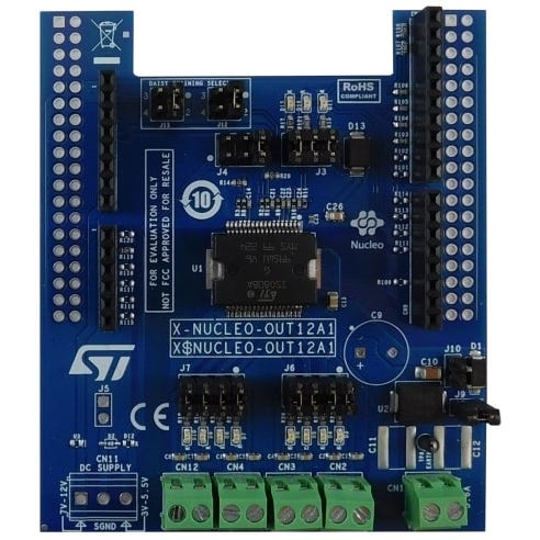
X-NUCLEO-OUT12A1
STMicroelectronics
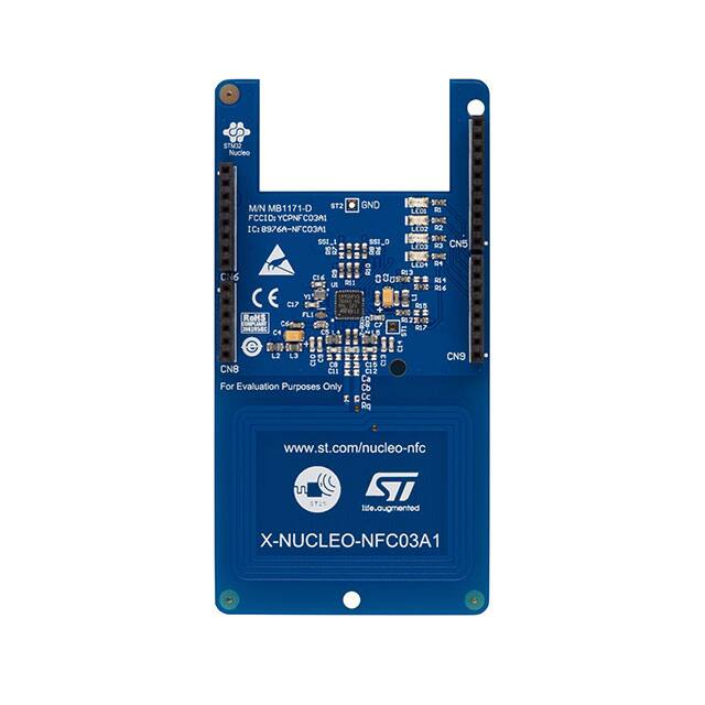
X-NUCLEO-NFC03A1
STMicroelectronics
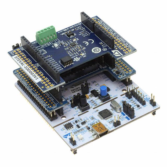
P-NUCLEO-IOD01A1
STMicroelectronics
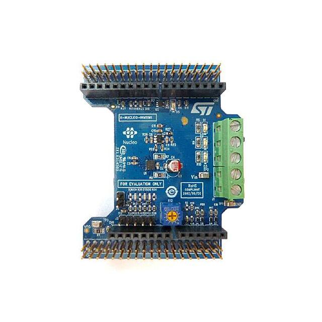
X-NUCLEO-IHM11M1
STMicroelectronics
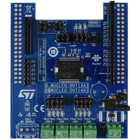
X-NUCLEO-OUT14A1
STMicroelectronics
X-NUCLEO-CCA02M2
STMicroelectronics
Нет недавно просмотренных товаров

MPU-6000EVB
TDK

INA226AIDGSR
Texas Instruments

TMS320F28335PTPQ
Texas Instruments
ISM330DHCX
STMicroelectronics

BAV99-7-F-CN
Unknown
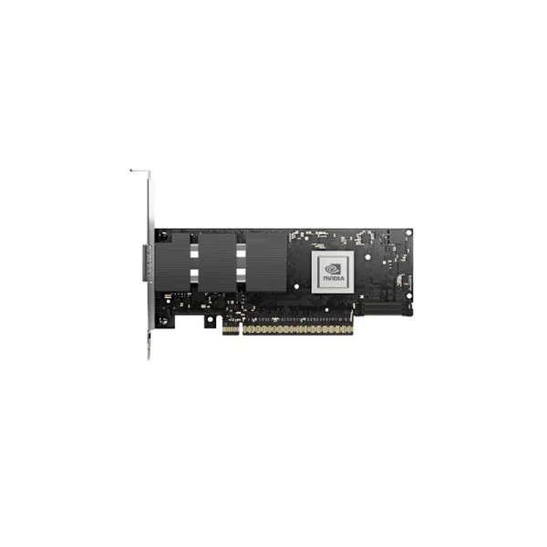
MCX75510AAS-NEAT
NVIDIA

TMS320F28379DZWTT
Texas Instruments
TMS320F28334ZJZS
Texas Instruments

CSDM65295
Texas Instruments
BQ27441DRZR-G1AG4
Texas Instruments