An Aluminum PCB Is a Three-Layer Thermal System, Not Just a Metal Core
An Aluminum PCB Is a Three-Layer Thermal System, Not Just a Metal Core
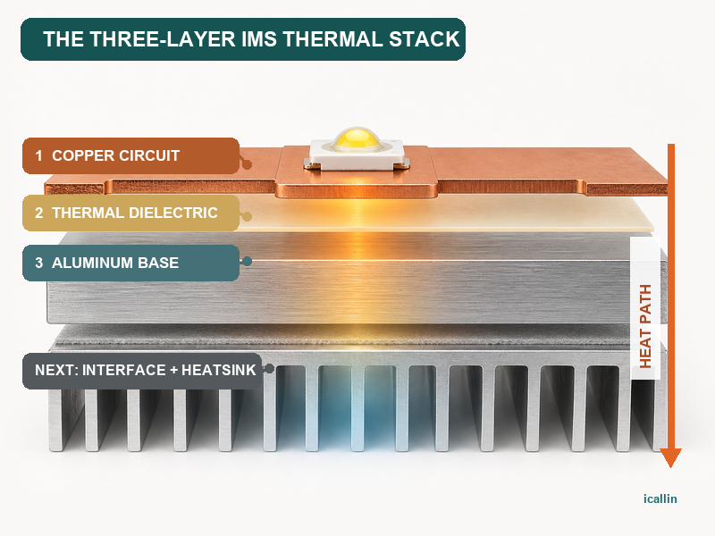
Calling a board an “aluminum PCB” directs attention to the thick metal backing, but that layer cannot carry a circuit or touch live copper directly. A practical insulated-metal substrate depends on three cooperating parts: copper for circuitry, a thermally conductive dielectric for electrical isolation, and an aluminum base for heat spreading and mechanical support.
The construction succeeds only when all three are selected as a system. Excellent aluminum cannot overcome a poorly matched dielectric, and a high-conductivity insulation layer cannot rescue an inadequate connection from the component to copper or from the metal base to the final heatsink.
What the Three-Layer Description Means
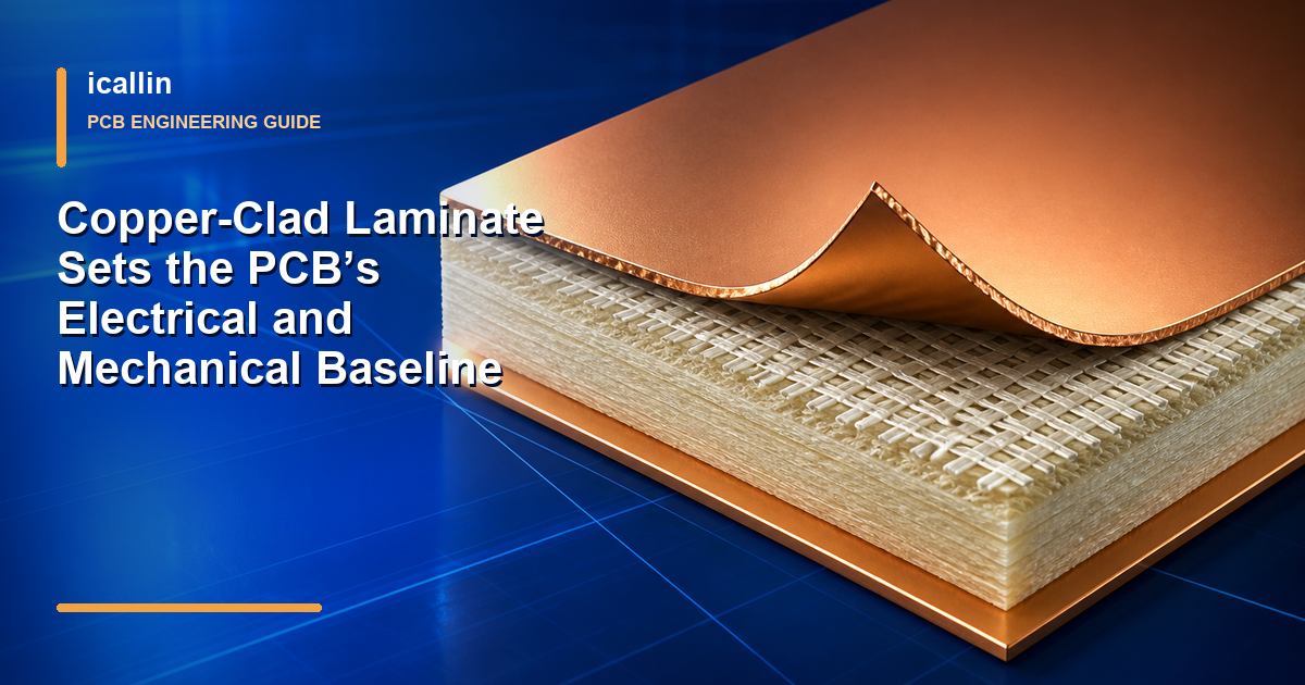
The simplest and most common aluminum PCB is a single-sided insulated-metal substrate. From the component side downward, its functional stack contains:
- an etched copper circuit layer;
- a thin electrically insulating, thermally conductive dielectric;
- a comparatively thick aluminum base plate.
Solder mask, surface finish, legend, solder, and components are added to the finished assembly, so “three-layer” does not mean the product literally contains only three materials. More complex multilayer metal-backed constructions also exist. The description is a useful model for understanding how electrical, insulation, and thermal duties are divided in a basic IMS board.
Layer 1: Copper Carries the Circuit
The copper layer performs the familiar PCB jobs: it forms traces, pads, planes, and component connections. It carries current and also spreads heat laterally around a hot package before that heat moves through the dielectric.
Copper geometry therefore affects both electrical and thermal performance. Wider areas can reduce electrical resistance and distribute heat over a larger footprint, while necked-down traces or small pads can concentrate temperature. Copper thickness may support current capacity and local spreading, but it does not remove the need to calculate allowable temperature rise or check fabrication limits.
Layout should give a power device a deliberate path into the board. The package’s thermal pad, solder joint, and copper land all sit upstream of the metal base. If this first connection is small, voided, or poorly placed, the rest of the stack cannot recover the lost thermal performance.
The circuit layer must also preserve creepage, clearance, voltage isolation, and assembly access. An aluminum base is not an automatic ground plane, and it should not be assumed electrically accessible unless the design intentionally provides and verifies that connection.
Layer 2: The Dielectric Separates Voltage and Transfers Heat
Between copper and aluminum is the layer that makes the structure possible. It prevents the circuit from shorting to the metal plate while giving heat a route through the board thickness. This dual role creates a central design tradeoff.
Electrical isolation tends to benefit from adequate dielectric thickness and validated breakdown performance. Heat transfer tends to benefit from a short path and a material engineered for low thermal impedance. The relevant choice cannot be made from thermal conductivity alone; dielectric thickness, tested thermal impedance, voltage stress, defects, aging, and the required safety margin all matter.
This layer is often the dominant board-level resistance between the copper and the metal base because aluminum and copper conduct heat much more readily. Small changes in the dielectric system can therefore change the temperature drop across an otherwise similar board. Use the selected material’s datasheet and the applicable test conditions, then verify the assembled thermal path rather than applying a generic “metal-core” value.
High-frequency behavior is also set largely by the dielectric system and geometry. An aluminum backing does not automatically create a low-loss RF substrate. Dk, Df, thickness tolerance, copper profile, grounding, and the intended frequency must be evaluated for the exact stack.
Layer 3: Aluminum Spreads Heat and Supports the Assembly
Once heat crosses the dielectric, the aluminum plate distributes it over a broader area. This lateral spreading reduces the concentration under an individual LED or power device and creates a larger surface that can contact a chassis, cold plate, or heatsink.
The plate also gives the board stiffness and can simplify mechanical integration. Its thickness, alloy, flatness, outline, holes, edge treatment, and mounting method should be considered with the enclosure. Those characteristics influence mass, rigidity, spreading, and the quality of contact with the next thermal surface.
Aluminum still does not dispose of heat by itself. If the base faces stagnant air or touches a housing through an uneven gap, temperature will continue to rise. Thermal interface material, contact area, surface flatness, fastener pattern, pressure, enclosure conduction, and airflow determine how effectively energy leaves the board.
| Functional layer | Primary duty | Design question that cannot be skipped |
|---|---|---|
| Copper circuit | Carries current and spreads heat near the source | Are pad area, copper geometry, thickness, and temperature rise adequate? |
| Thermal dielectric | Isolates voltage while passing heat to metal | Do thickness, thermal impedance, breakdown, and material data fit the application? |
| Aluminum base | Spreads heat and supports mounting | Is there a controlled path from the plate into a chassis, heatsink, or ambient? |
Table 1: Each layer removes a different bottleneck; none can replace the other two.
Follow the Complete Heat Path
The meaningful thermal system begins inside the semiconductor, not at the aluminum. Heat moves from the junction through the package and solder connection, into the copper, across the dielectric, through the aluminum, and then across a mechanical interface before reaching a heatsink, housing, liquid loop, or ambient air.
Every step adds thermal resistance. The largest bottleneck may be inside the package, across the dielectric, at a voided solder joint, or between the base and enclosure. A thermal image of the exposed copper side can reveal hot regions, but it does not directly prove junction temperature or the quality of hidden interfaces. Reflective metal can also distort infrared readings unless emissivity is controlled.
Start with worst-case device loss and allowable junction temperature. Estimate the resistance of the full path, including the final cooling structure, and then test representative hardware at realistic load, ambient temperature, airflow, orientation, and enclosure condition.
Applications That Fit This Construction
LED Light Engines
LED arrays combine multiple heat sources in a compact area. Copper gathers heat from the packages, the dielectric passes it to the plate, and the aluminum spreads it into a luminaire body or external heatsink. This structure is well suited when the mechanical housing already provides a broad cooling surface.
Power Conversion and Motor Control
Switching devices, rectifiers, regulators, resistors, and drivers can create concentrated losses in converters, power supplies, chargers, inverters, and motor controllers. A single-sided IMS board can couple several sources to one mounting plate while retaining an electrically isolated circuit layer.
Automotive and Industrial Modules
Lighting modules, compact actuators, power stages, and industrial controls may benefit when the PCB mounts directly to a metal enclosure. The complete design still needs environmental, vibration, insulation, thermal-cycle, and qualification evidence; aluminum construction alone does not confer an automotive or industrial rating.
Selected RF, Consumer, and Medical Hardware
RF power devices, audio amplifiers, display backlights, imaging equipment, and other thermally dense functions can use metal-backed boards when the electrical stackup and product requirements permit. RF suitability depends on controlled dielectric properties. Medical suitability depends on the complete safety architecture, isolation, leakage control, risk management, and verification rather than the substrate name.
When Another Board Structure May Fit Better
Aluminum PCB is not a default upgrade for every warm design. A conventional multilayer FR-4 board with copper planes, thermal vias, and an attached heatsink may provide easier dense routing or double-sided component placement. A ceramic substrate may suit applications needing different isolation, temperature, or expansion behavior. Direct-bonded or other advanced structures may be justified at still higher power density.
Basic single-sided IMS also constrains via and routing options. Holes through a conductive metal base require controlled isolation, and complex plated-through or multilayer features depend on specialized constructions and fabricator capability. Check the actual stackup and process rather than assuming ordinary FR-4 design rules transfer unchanged.
Specify the System, Not Only the Metal
Before releasing an aluminum PCB, define the copper weight and geometry, dielectric material and thickness, thermal impedance or conductivity data under a stated method, electrical breakdown requirements, aluminum alloy and thickness, surface finish, solder mask, outline, and mechanical features. Confirm tolerances and current capabilities with the selected fabricator.
Then review how the finished board mounts. Specify interface material where needed, keep contact surfaces flat and clean, distribute clamping pressure, maintain electrical isolation, and account for tolerances that could create an air gap. Validate solder quality and the final thermal assembly under worst-case conditions.
An aluminum PCB works because three layers divide the problem intelligently. Copper connects the circuit and gathers heat, the dielectric preserves isolation while allowing heat to cross, and the aluminum base spreads that heat into a larger mechanical structure. Treating those roles as one coordinated system produces a credible thermal path; selecting a “metal core” by name alone does not.
Need Help With PCB Manufacturing or PCBA Assembly?
Share your PCB manufacturing or PCBA assembly requirements with icallin through our dedicated quotation page.