PCB Materials Guide: Substrates, Copper and Solder Mask
Understanding PCB Materials: Substrates, Copper, Solder Mask, and Adhesives
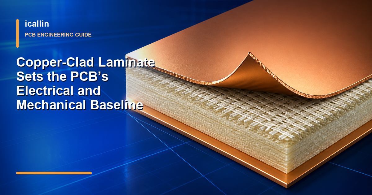
A printed circuit board is more than a pattern of copper tracks. It is a laminated system in which the substrate, copper foil, solder mask, markings, and bonding layers must work together. Each material influences electrical behavior, heat resistance, mechanical strength, moisture performance, and production cost.
Key Takeaways
- FR-4 remains the usual starting point for reliable, economical general-purpose boards.
- Low-loss laminates are considered when an RF or high-speed design cannot tolerate the losses or dielectric variation of ordinary FR-4.
- Increasing copper weight can support more current and spread more heat, but it also affects trace geometry and fabrication limits.
- High-Tg laminates can improve thermal robustness, especially in multilayer assemblies exposed to demanding soldering or operating cycles.
- Liquid photoimageable solder mask is widely used because it combines fine imaging with good protection, while the best color and formulation depend on the application.
Materials That Make Up a PCB
Most rigid and flexible circuit boards contain several material systems rather than one single “PCB material.” The base laminate provides mechanical support and electrical insulation. Copper forms the conductive paths. Solder mask protects the finished circuitry, and a printed legend helps people identify components and connection points. In multilayer or flexible constructions, bonding films and resin-rich reinforcement hold the layers together.
Selecting these materials requires tradeoffs. A low-loss laminate may cost more or need a different fabrication process, while thick copper can make fine spacing harder to produce. The stack should therefore reflect the product’s electrical, thermal, mechanical, and environmental demands.
1. Substrates
The substrate is the insulating foundation beneath the circuitry. Woven glass reinforced with epoxy resin, commonly identified as FR-4, is the most familiar choice for rigid PCBs. Other families include CEM-1 and CEM-3 composite materials, polyimide for flexible or thermally demanding boards, and engineered low-loss laminates for RF and high-speed signals.
Several properties help determine whether a substrate is suitable:
- Dielectric constant (Dk): Dk affects signal velocity, impedance, and the trace dimensions needed for controlled-impedance routing. It should be considered with frequency and test method. Dielectric loss is more directly associated with dissipation factor (Df), so Dk alone does not describe total signal loss.
- Glass transition temperature (Tg): Tg marks a change in the resin system’s mechanical and expansion behavior; it is not the board’s maximum operating temperature. A higher-Tg grade can provide useful stability during lead-free assembly and repeated thermal exposure.
- Coefficient of thermal expansion (CTE): The laminate, copper, vias, solder joints, and mounted components expand at different rates. Excessive expansion, particularly through the board thickness, can contribute to via fatigue, cracking, or delamination during thermal cycling.
- Moisture absorption: Water taken up by the laminate can affect electrical properties and increase the risk of damage during rapid heating. Humid, outdoor, or high-reliability products may need lower-absorption materials and controlled storage or baking procedures.
- Electrical insulation and mechanical strength: The material must maintain adequate separation between conductors while supporting the board through assembly and service.
- Process compatibility: The board shop must be able to laminate, drill, plate, and finish the material within the required design rules.
Material names alone do not provide a complete specification. Two FR-4 products, for example, can have different Tg, Dk, Df, CTE, moisture behavior, and thickness tolerances. Designers should therefore confirm the actual laminate data and approved stackup rather than relying only on a family label.
2. Copper Foils
Copper foil becomes the planes, pads, and traces that distribute power and carry signals. Two broad production routes are common: rolled copper and electrodeposited copper. Both are available in multiple thicknesses and surface profiles, so the process name should not be treated as a guarantee of a particular weight.
Copper selection usually centers on three considerations. First, thickness affects the cross-sectional area of a trace and therefore its resistance, current capability, and temperature rise. Second, conductivity depends on the copper grade and finished geometry. Third, surface profile matters because the foil must bond reliably to the laminate; at high frequencies, a rougher conductor surface can also increase insertion loss. The selected foil treatment must suit both the laminate and the electrical performance target.
3. Solder Mask
Solder mask is the polymer coating that covers most finished copper while leaving pads and other intended contact areas exposed. During assembly it reduces accidental solder bridging, and in service it helps protect conductors from contamination, handling damage, and unintended electrical contact.
Important selection factors include chemical resistance, adhesion to copper and laminate, electrical insulation, imaging resolution, color, and compatibility with the assembly temperature profile. Liquid photoimageable, dry-film, and thermally cured systems are common, but exact properties depend on the individual product and cure process.
4. Silkscreen and Board Legends
The printed legend does not carry current, yet it has an important practical role. Reference designators, polarity marks, connector labels, test-point names, warning symbols, and component outlines help technicians assemble, inspect, test, and service the product.
Component-side markings guide assembly, while labels on the opposite side may identify connectors, board revisions, certification symbols, or product information. In every case, text must remain readable after solder mask, component placement, cleaning, and normal handling.
5. Bonding and Adhesive Materials
Bonding materials keep the PCB construction intact. In a conventional rigid multilayer board, prepreg—glass cloth impregnated with partially cured resin—typically bonds copper-clad cores together and establishes dielectric spacing. Epoxy-based, acrylic, polyurethane, or polyimide bonding systems may appear in flexible circuits, stiffener attachment, coverlays, or other specialized constructions.
The correct bonding material must retain adhesion over the expected temperature range and resist the moisture and chemicals encountered during production and use. Flexibility, cure conditions, dielectric properties, and compatibility with adjacent materials also matter. A strong adhesive in isolation can still be a poor choice if its expansion or cure cycle is incompatible with the rest of the stack.
Common PCB Substrate Families
FR-4
FR-4 is a flame-retardant family of glass-reinforced epoxy laminates. Its popularity comes from a practical combination of electrical insulation, mechanical strength, process familiarity, availability, and cost. It can be used for simple single- and double-sided boards as well as complex multilayer designs.
General-purpose FR-4 suits many controllers, embedded systems, and moderate-speed digital designs. For multiple reflow cycles, high layer counts, sustained heat, tight impedance control, or faster edge rates, the exact grade still needs review.
High-Tg FR-4 uses a resin system with a higher transition temperature than a standard grade. This can improve resistance to the mechanical stress produced by assembly heat and operating cycles. It does not automatically guarantee low loss, low CTE, or suitability at a particular service temperature, so Tg should be evaluated alongside the other published properties.
Polyimide
Polyimide materials are widely associated with flexible and rigid-flex circuits because they can form thin insulating layers that tolerate bending. They also offer useful thermal endurance for aerospace, industrial, and other demanding applications. These characteristics allow lightweight interconnects to fold through compact products or flex during installation and, when designed for it, during operation.
The tradeoffs include higher material and processing cost than typical FR-4 and the need to manage moisture carefully. Flex performance also depends on copper type, bend radius, layer count, adhesive system, and how traces are routed through the bend area. Choosing polyimide is therefore the beginning of a flex design decision, not a complete solution by itself.
Low-Loss RF and High-Frequency Laminates
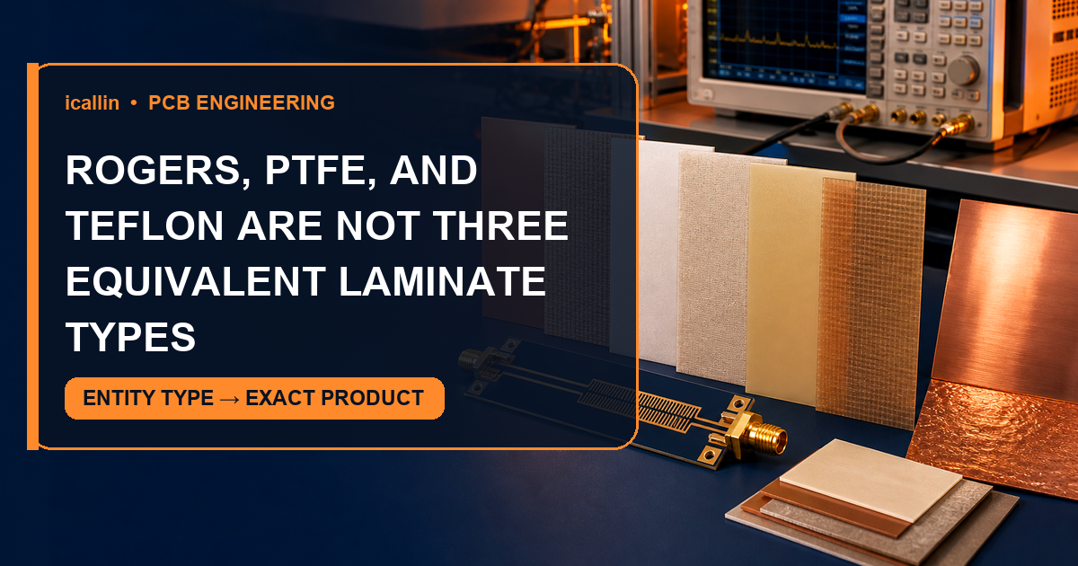
RF, microwave, antenna, and high-speed data designs may require laminates with lower Df and more tightly controlled dielectric behavior than general-purpose FR-4. Stable Dk helps the designer predict impedance and phase behavior, while lower dielectric loss can reduce attenuation over long routes or at high frequencies.
There is no universal frequency at which every design must change materials. Route length, allowable loss, stackup, copper profile, modulation, impedance tolerance, thermal requirements, and budget all influence the decision. These laminates may also require special preparation, drilling, bonding, or surface treatment, so electrical benefit must be evaluated together with fabrication compatibility.
CEM-1 and CEM-3
CEM materials combine resin with paper and/or glass reinforcement. CEM-1 is often associated with economical single-sided boards, while CEM-3 can be used in some double-sided applications. They can be appropriate where cost and straightforward circuitry dominate, but they do not provide the same universal replacement path as FR-4 for complex multilayer, high-temperature, or tightly controlled high-speed designs.

Figure 1: Each layer contributes a different electrical, thermal, mechanical, or protective function.
Rolled and Electrodeposited Copper Foil
Rolled Copper
Rolled copper foil is produced by mechanically reducing copper through repeated rolling. Its grain structure and fatigue behavior make it a frequent choice for flexible circuits that must survive repeated bending. Smooth or specially treated rolled foils can also be useful where conductor surface profile matters to high-frequency loss.
This does not mean rolled foil is always the thinnest, smoothest, or best electrical option. Copper weight, surface treatment, annealing, and the finished laminate construction must still be specified for the application.
Electrodeposited Copper
Electrodeposited foil is formed electrochemically on a rotating drum and then treated for bonding. It is widely used in rigid printed circuit boards and is available in many weights and profile grades. Standard, low-profile, and very-low-profile variants allow designers and fabricators to balance laminate adhesion, etching behavior, cost, and high-frequency performance.
Understanding Copper Weight
Copper thickness is often expressed in ounces per square foot. One-ounce and two-ounce copper are common reference points, but the finished copper thickness also includes plating on outer layers and can vary with process. Moving from 1 oz to 2 oz increases conductor area, which can reduce resistance and temperature rise for the same trace width. It may also require wider clearances, change impedance geometry, and make fine features more difficult.
Current capacity should not be selected from copper weight alone. Trace width, allowable temperature rise, adjacent planes, airflow, and the operating environment also matter.
Common Solder Mask Systems
Liquid Photoimageable Solder Mask
Liquid photoimageable solder mask, usually shortened to LPI, is applied as a liquid coating and patterned by imaging and development before final cure. Its ability to define relatively fine openings has made it the most common choice for many contemporary rigid boards. Formulations are offered in green and numerous other colors, with properties that vary by supplier and process.
Color should be selected for inspection, optical behavior, markings, thermal exposure, and appearance. Green is widely used and often provides good visual contrast, but it is not automatically superior for every product. Black, white, blue, red, and other finishes may be appropriate when enclosure design, light reflection, sensors, cameras, or branding influence the decision.
Dry-Film Solder Mask
Dry-film solder mask is supplied as a solid film and laminated onto the board before imaging and development. It can provide controlled coating thickness and may suit particular feature or surface requirements. Compared with LPI, availability, cost, achievable definition, and preferred process depend strongly on the fabricator and the specific dry-film product.
Thermally Cured Solder Mask
Thermally cured masks are liquid coatings hardened through a heat-based cure. They can offer useful adhesion and chemical resistance in suitable applications, but performance limits are formulation-specific. They should be selected from qualified material data rather than a single assumed temperature rating.
Whichever system is chosen, pad openings, mask dams, clearances, surface finish, component pitch, and the assembly process must be reviewed together. A good coating cannot compensate for openings that violate the manufacturer’s imaging capability.
Adhesives and Prepreg in PCB Construction
Epoxy resin systems are common because they can combine adhesion, insulation, chemical resistance, and thermal stability. In rigid multilayer boards, epoxy-glass prepreg is far more typical than applying a separate liquid adhesive between every layer. During lamination, heat and pressure allow the resin to flow, fill the surrounding features, and cure into a stable dielectric layer.
Acrylic adhesives are frequently encountered in flexible-circuit bonding films and coverlays. They can provide flexibility and useful environmental resistance, although their thermal, electrical, and dimensional properties must match the intended flex construction. Polyurethane adhesives offer flexibility and bonding strength for selected assemblies, but they are not a universal default for PCB layer lamination.
The bonding choice influences more than whether layers remain attached. It controls dielectric spacing, resin flow around copper, dimensional movement, moisture behavior, and the ability to endure soldering and thermal cycling. Designers should define the required construction, while the board manufacturer confirms a compatible material set and lamination cycle.
FAQ About PCB Materials
What is the most commonly used PCB substrate, and why?
FR-4 is the standard starting point for most rigid boards because it offers a strong balance of electrical insulation, mechanical strength, flame resistance, process maturity, availability, and cost. It covers a wide range of consumer and industrial designs. The exact FR-4 grade still needs to match the required Tg, electrical performance, thickness, and reliability targets.
When should a low-loss laminate be chosen instead of FR-4?
Consider a low-loss RF or high-speed laminate when analysis or testing shows that ordinary FR-4 cannot meet the loss, impedance, phase, or dielectric-stability requirement. The decision should be based on frequency together with route length, edge rate, power, copper profile, stackup, environmental conditions, and allowable budget—not on one fixed frequency threshold.
What is the difference between standard and high-Tg FR-4?
High-Tg FR-4 has a resin transition temperature above that of a standard formulation and can be more resistant to expansion-related stress during assembly and service. Published Tg values vary by product and test method. High Tg is valuable, but it does not by itself define operating temperature, Dk, Df, CTE, or moisture performance.
How does copper weight affect PCB performance?
Thicker copper provides more conductive cross-sectional area, which can support higher current or reduce temperature rise when the rest of the geometry is unchanged. It can also complicate fine-line etching, minimum spacing, and controlled-impedance design. Copper weight should therefore be chosen with trace width, plating, thermal limits, voltage clearance, and fabrication rules.
Which solder mask color is recommended?
Green LPI is common and often inspection-friendly, so it is a sensible default for many boards. It is not a universal technical requirement. Select color by considering automated and manual inspection, silkscreen contrast, optical sensors, lighting, heat exposure, enclosure appearance, and which qualified formulations the chosen manufacturing process supports.
Conclusion
PCB performance depends on the interaction of every material in the stack. FR-4 may be the right economical foundation for a general-purpose controller, while polyimide enables a flexible interconnect and a low-loss laminate protects a demanding RF path. Copper weight, foil profile, solder mask, markings, prepreg, and bonding films then complete the construction.
The most reliable choice comes from defining what the board must carry, how hot it will become, what environment it will face, and how precisely its signals must behave. Comparing those needs with actual material data—and confirming the complete stack with the manufacturer—produces a board that is practical to build and dependable in service.