


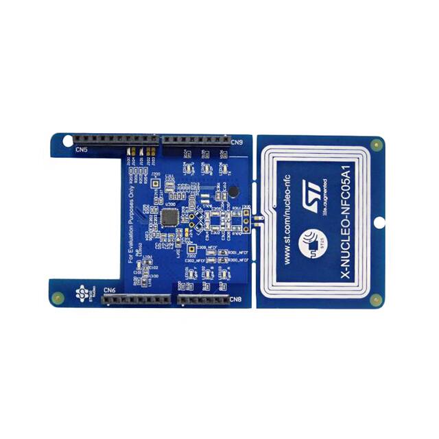
X-NUCLEO-NFC05A1
STMicroelectronics
Yes. X-NUCLEO-OUT17A1 by STMicroelectronics is available for RFQ. Submit your required quantity and our team will confirm real-time stock, lead time, and volume pricing.
Pricing for X-NUCLEO-OUT17A1 can vary by order quantity, market availability, date code, packaging, and delivery destination. Request a quote to receive the latest volume pricing.
X-NUCLEO-OUT17A1 is a STMicroelectronics Software with Core Product: IPS8200HQ-1 and Packing Type: Not Applicable. Review the product details or submit an RFQ if you need confirmation before purchase.
Our sales team usually responds within 24 hours after receiving your RFQ. The quote may include stock status, unit price, lead time, shipping options, and available alternatives.
If stock is confirmed, in-stock parts can usually ship within 1–2 business days. Final lead time depends on quantity, stock source, and delivery destination.
Yes. If X-NUCLEO-OUT17A1 is unavailable, obsolete, or does not meet your required lead time, we can help check similar STMicroelectronics Software parts or compatible alternatives.
Looking for Pricing? Contact us for volume pricing.
Fast Dispatch: Ships in 5-7 days(in-stock parts within 1-2 days)
Unishop Global Export: 1-7 days, $40.00
Guaranteed Delivery: Door-to-door in 30 days
Compliant Worldwide Shipping: DHL, FedEx, SF, and UPS.
IMPORTANT NOTICE
Quotations are subject to stock availability and may vary with market conditions. Prices and lead times are not guaranteed until a purchase order is confirmed. Ensure your contact details are correct to avoid delays in response.
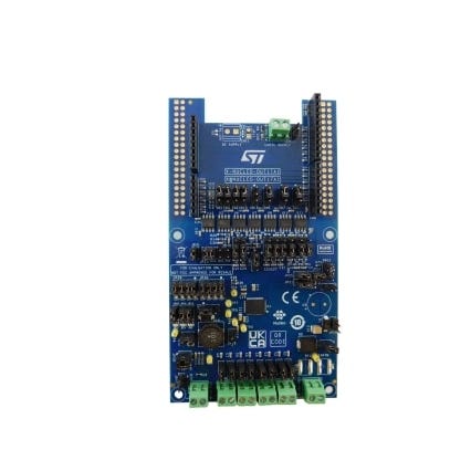
The X-NUCLEO-OUT17A1 is an industrial digital output expansion board for STM32 Nucleo. It provides a powerful and flexible environment for the evaluation of the driving and diagnostic capabilities of the IPS8200HQ-1 octal high-side, smart power, solid-state relay in a digital output module connected to 1.0 A industrial loads.
The X-NUCLEO-OUT17A1 interfaces with the microcontroller on the STM32 Nucleo via STISO620 and STISO621 and Arduino® UNO R3 connectors.
The user can select which driving mode controls the IPS8200HQ-1: parallel (SEL2 = L by JP21 = open) or SPI (SEL2 = H by JP21 = closed).
In the case of SPI selection, the user can select the communication protocol between 8 bits (SEL1 = L by JP22 = open) or 16 bits (SEL1 = H by JP22 = closed).
The VCC supply pin of the IPS8200HQ-1 is provided by the connector CN1, while the loads (driven by the 8 output channels of the IPS8200HQ-1) can be connected between the connectors CN2, CN3, CN4, CN12, and the pin 2 of the connector CN1.
The on-board digital isolators (STISO620 and STISO621) feature the 2.8k VRMS (4k VPK) galvanic isolation between the two application sides: logic and process sides.
The logic side is the application side of the MCU and it is supplied by the VISO_L rail (3.3 or 5.0 V). VISO_L can be supplied by an external power supply connected to CN13 or, alternatively by the pin 4 (SW1 = close 1-2) or pin 5 (SW1 = close 2-3) of CN6.
The process side is the application side of the industrial loads and it is supplied by the VCC and VISO_P rails. The VISO_P (3.3 or 5.0 V) is usually supplied by the VREG rail (JP31 = closed) that can be generated by the step-down embedded in the IPS8200HQ-1 (SW17 = close 1-2, JP20 = closed, JP15 = closed and JP28 = close 2-4 (VREG = 3.3 V) or JP28 = 1-3 (VREG = 5.0 V)).
Alternatively, VREG can be provided by an external power supply connected to CN14 (SW17 = close 2-3, JP20 = open, JP15 = open).
In parallel driving mode (active with the default jumper and switch settings) the application board can work even without any Nucleo board: in this case, the user must provide the process side voltage (usually 24 V) by the CN1 and the VISO_L (usually 3.3 V) by the CN13. The INX signals, available on CN5[1, 2, 3], CN8[4] and CN9[3, 5, 7, 8], drives on/off the correspondent OUTX connected to the loads on the process side.
The INX pins can be driven low/high swinging between 0V and VISO_L. The activation of each OUTX (OUT1… OUT8) can be monitored by the green LEDs DOX (DO1… DO8).
The activation of the three diagnostic pins (TWARN, PGOOD, FAULT) can be visualized on the correspondent red LEDs (D11, D12, D13, respectively) or monitored by an oscilloscope on CN8[5], CN5[9], CN5[10].
The SPI driving mode can be set by changing the default configuration (JP21 = close; SW4, SW5, SW6, SW7, SW9, SW10, SW11, SW12, SW13, SW14, SW15, SW20 = close 2-3, SW18 = close 1-2). The SPI-8bits is the default mode (JP22 = open), while the SPI-16bits mode can be activated by JP22 = close.
In SPI driving mode it is also possible to activate the MCU freeze detection feature by setting SW3 = close 2-3.
The expansion board can be connected to either a NUCLEO-F401RE or a NUCLEO-G431RB development board. In this case the companion firmware X-CUBE-IPS detects the selected configuration (GPIO, SPI-8bits, SPI-16bits) by reading the signals SEL2_L and SEL1 from CN8[1] and CN8[6]. The activation of the MCU freeze feature is detected by WDEN(in) on CN9[4].
It is also possible to evaluate a system composed of a X-NUCLEO-OUT17A1 stacked on other expansion boards. In fact, SPI driving mode allows the daisy-chaining communication with another X-NUCLEO-OUT17A1 stacked through the Arduino connectors: the two stacked boards must be configured with SW6, SW18 = close 2-3 on one board, and SW6, SW18 = close 1-2 on the other board.


X-NUCLEO-NFC05A1
STMicroelectronics

X-NUCLEO-53L7A1
STMicroelectronics

X-NUCLEO-OUT16A1
STMicroelectronics

X-NUCLEO-PM33A1
STMicroelectronics
X-NUCLEO-NFC12A1
STMicroelectronics
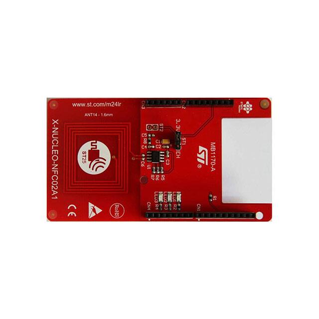
X-NUCLEO-NFC02A1
STMicroelectronics
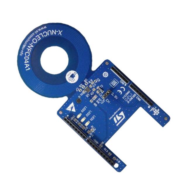
X-NUCLEO-NFC04A1
STMicroelectronics
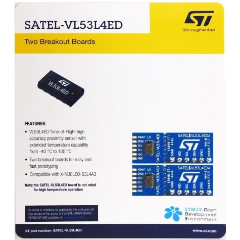
SATEL-VL53L4ED
STMicroelectronics
X-NUCLEO-60K1A1
STMicroelectronics
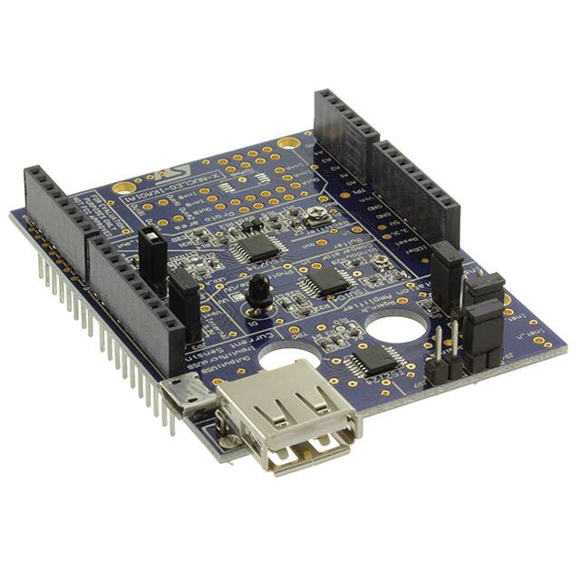
X-NUCLEO-IKA01A1
STMicroelectronics
No recently viewed products

MT25QU256ABA1EW7-0SIT
Micron
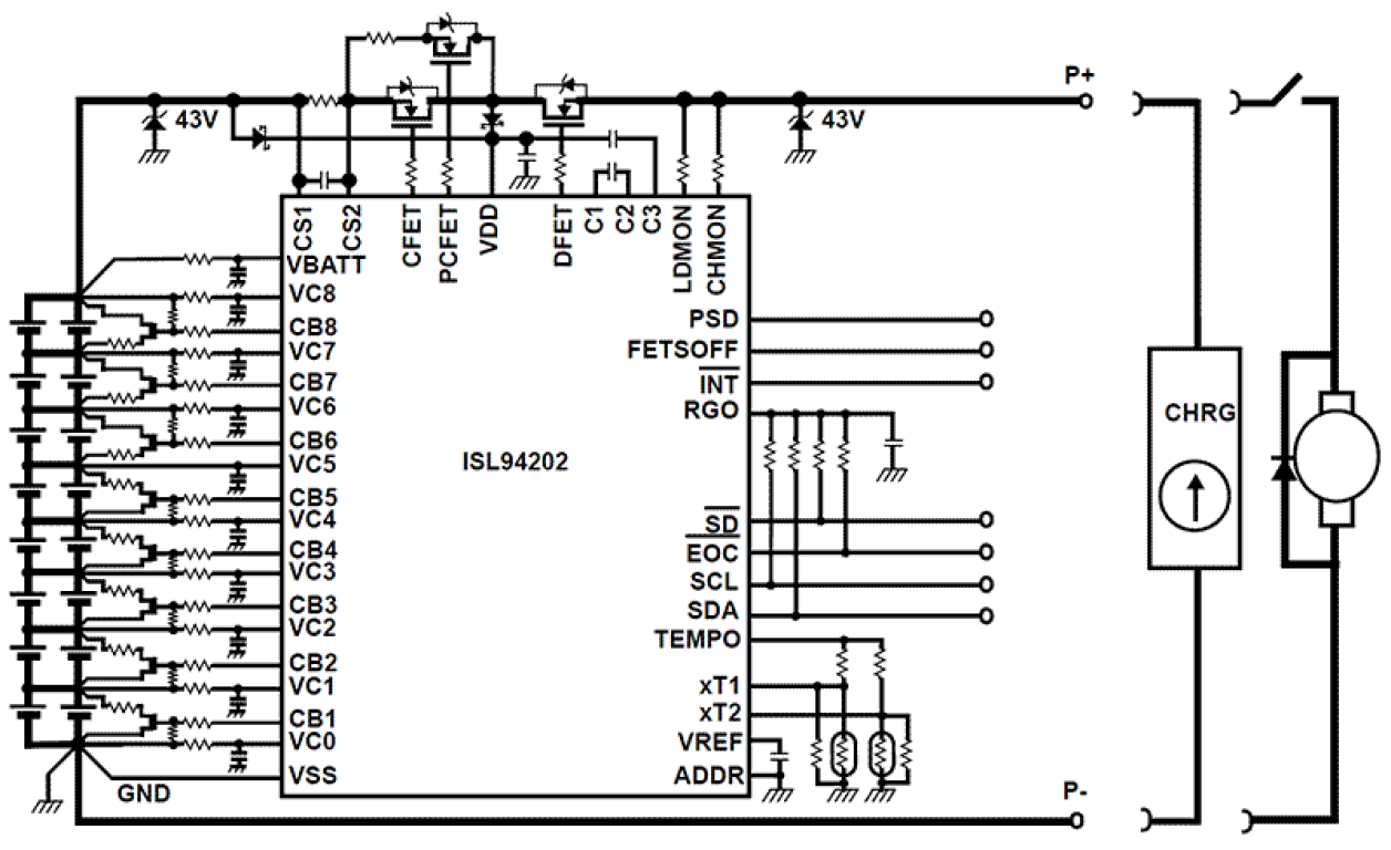
ISL94202IRTZ-T
RENESAS

PMEG4010CEGW-QJ
NEXPERIA

MT29F16G08ABACAWP-ITZ:C
Micron

FS32K118LFT0VLHT
NXP

CSDM65295
Texas Instruments

H5AN8G8NCJR-XNC
SK HYNIX
MT60B2G8HB-48B:A
Micron

K4RAH165VB-BCWM
SAMSUNG

MTFC8GAKAJCN-4M IT
Micron