When FR-4 Is the Right PCB Material—and When It Is Not
FR-4 Is the Default PCB Material Until Heat or Frequency Says Otherwise
FR-4 is the sensible starting material for most rigid printed circuit boards. It is familiar to fabricators, mechanically useful, electrically insulating, widely available, and economical. Keep it as the default while the chosen grade meets the design's loss, temperature, mechanical, environmental, and safety requirements. Change materials only when a measured requirement crosses one of those boundaries.
That conclusion is more useful than asking whether FR-4 is universally “best.” FR-4 is a family of glass-reinforced epoxy laminates, not one fixed formulation. Two grades can differ substantially in glass transition temperature (Tg), Z-axis expansion, decomposition temperature, dielectric constant (Dk), dissipation factor (Df), moisture absorption, and long-term thermal rating. The decision is therefore between qualified material systems and stackups, not merely between familiar names.
Why FR-4 Earned Its Place as the Default
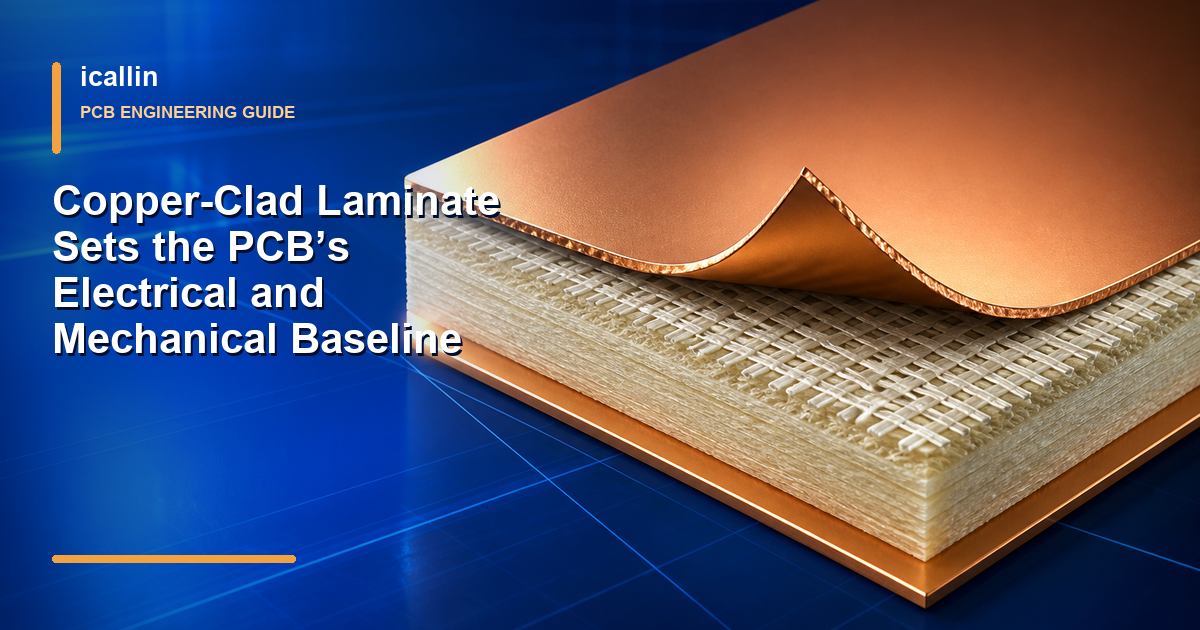
Woven glass gives an FR-4 laminate much of its in-plane strength and dimensional stability. The cured epoxy resin binds that reinforcement and insulates adjacent copper features. In a multilayer board, cores and prepregs create the dielectric spacing between signal and plane layers while supporting plated holes, pads, and mounted components.
This construction fits established imaging, etching, drilling, desmear, plating, solder-mask, and assembly processes. That process maturity is a major advantage: designers can usually obtain standard thicknesses and multilayer stackups without introducing a specialty-material workflow.
FR-4 also covers more performance territory than the phrase “standard FR-4” suggests. General-purpose, high-Tg, low-CTE, and lower-loss epoxy-glass products all exist. Moving to a better-qualified FR-4 grade may solve an assembly-reliability problem without forcing a completely different substrate family.
The designation should not be treated as a complete safety certificate. Flame performance, minimum qualified thickness, temperature rating, and other recognitions belong to the exact laminate and finished construction. Confirm those records instead of assuming every material sold as FR-4 has identical ratings.
Keep FR-4 When the Evidence Says It Still Fits
FR-4 remains a strong choice when all of the following are true:
- The predicted and measured channel loss stays inside the interface budget across frequency, route length, temperature, and manufacturing tolerance.
- The approved stackup can hold the required impedance without impractical trace dimensions.
- Local board temperature and long-term exposure remain within the laminate's validated limits.
- Reflow, wave soldering, rework, and thermal cycling do not create unacceptable expansion or delamination risk.
- The product is rigid, and its thickness and support points satisfy shock, vibration, connector, and enclosure loads.
- Heat can leave power components through a complete path that may include copper, thermal vias, interface material, airflow, a chassis, or a heatsink.
- Moisture, chemicals, voltage stress, and flame requirements match the exact grade and protective system.
This is a requirements check, not a frequency shortcut. A short digital interconnect with fast edges may work on a carefully designed FR-4 stackup, while a long lower-frequency RF path may exceed its loss budget. Likewise, a high-Tg label does not prove that a laminate can operate continuously near its Tg.

Trigger 1: Loss or Dielectric Control Requires a High-Frequency Laminate
Frequency alone does not set a universal point where FR-4 stops working. The meaningful trigger is failure to meet insertion-loss, phase, skew, impedance, or temperature-stability targets with an available FR-4 construction.
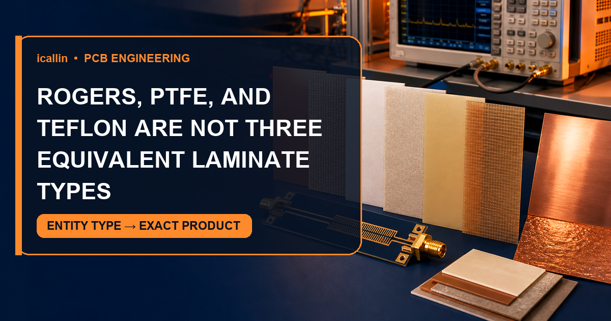
For RF, microwave, antenna, or long high-speed channels, compare Df at the relevant frequency, design Dk and its tolerance, Dk stability over temperature, copper-foil profile, dielectric thickness tolerance, and moisture behavior. A low-loss hydrocarbon/ceramic or PTFE-based laminate may provide lower attenuation and more predictable phase behavior. Copper roughness can become part of the loss budget as fields concentrate near the conductor surface.
Specialty laminates bring manufacturing consequences. Some require different bonding films, surface preparation, drilling, plasma treatment, or lamination cycles. A hybrid stackup can confine the specialty material to critical layers, but resin compatibility, registration, CTE, and processing must be approved by the board fabricator before layout is frozen.
Trigger 2: Temperature or Heat Flow Exceeds the FR-4 Solution
Separate three thermal questions because they lead to different choices.
First, can the board survive assembly and thermal cycling? If the problem is expansion stress during repeated lead-free reflow or service cycles, a thermally robust FR-4 grade may be enough. Compare Tg using the same test method, then review Z-axis CTE, total expansion, Td, T260/T288, moisture behavior, and the actual via construction. Tg marks a change in resin behavior; it is not a melting point or maximum continuous operating temperature.
Second, can the material tolerate long-term operating heat? Use the laminate's long-term thermal data, applicable relative thermal index, and product qualification evidence. A high-Tg value alone does not establish service life. High-temperature polyimide or another specialty organic laminate may be appropriate where sustained exposure, chemicals, or repeated thermal excursions exceed the validated FR-4 system.
Third, can heat reach a useful sink? When a power device needs a short through-thickness thermal path to a chassis or heatsink, an insulated metal substrate can be more effective than ordinary FR-4. The metal core is only one part of that path; the thin dielectric, copper area, thermal interface material, mounting pressure, and heatsink still control junction temperature. Metal-core construction is not automatically the right answer for complex multilayer routing or RF performance.
Ceramic substrates become attractive at still higher power density, isolation voltage, temperature, or CTE-matching demands. Alumina, aluminum nitride, and silicon nitride constructions offer very different thermal and mechanical properties. They can provide strong heat spreading and closer CTE alignment to semiconductor dies, but they are more brittle, costlier, and governed by different conductor, via, panel, and assembly rules.
Trigger 3: The Interconnect Must Bend
A rigid FR-4 board can be made thin, but thin does not make it a flex circuit. If the product must fold during installation, move repeatedly, pass through a hinge, or fit a three-dimensional envelope, a polyimide-based flexible or rigid-flex construction is normally the relevant path.
Flexibility depends on the entire construction: dielectric and adhesive thickness, rolled or electrodeposited copper, trace direction, bend radius, layer count, coverlay, stiffener transitions, and the number of bend cycles. Do not choose flex solely to reduce thickness, and do not expect an unsupported thin FR-4 section to survive repeated bending.
Trigger 4: The Environment Demands a Different Material System
Humidity, corrosive chemicals, contamination, high voltage, radiation, and severe thermal shock can expose limits that are invisible at room temperature. Sometimes the right response is a better FR-4 grade plus conformal coating, spacing, sealing, or process control. In other cases, polyimide, fluoropolymer, ceramic, or another qualified substrate is necessary.
The decision must include the complete protection system. A chemically resistant laminate cannot compensate for exposed copper, an unsuitable surface finish, poor creepage, a moisture-sensitive component, or an enclosure that traps contamination.
A Practical Material Decision Table
| Design evidence | Stay with FR-4 when… | Consider switching when… |
|---|---|---|
| Signal loss and phase | The verified channel meets margin across tolerance and temperature | Df, Dk variation, copper roughness, or route length breaks the channel budget |
| Assembly and cycling | Tg, CTE, Td, T260/T288, moisture, and via data support the profile | Expansion or delamination risk remains unacceptable with a robust FR-4 grade |
| Continuous heat | Long-term material data and measured board temperature support service life | Sustained temperature exceeds the qualified organic laminate system |
| Heat removal | Copper, vias, airflow, chassis, or heatsink maintain junction temperature | A short insulated path through metal or ceramic is needed for the power density |
| Mechanics | The board stays rigid and fits the supported enclosure | The interconnect must fold, flex repeatedly, or conform to a moving assembly |
| Environment | The selected grade and protection withstand exposure | Chemicals, moisture, voltage, or thermal shock exceed the validated system |
Table 1: A material change should answer a specific failed requirement, not a vague preference | Compiled by: icallin.com
What to Put in the Material and Fabrication Notes
Do not release a drawing that says only “FR-4.” Identify the approved laminate or specification sheet, finished board thickness and tolerance, copper construction by layer, flame and safety requirements, and the controlled-impedance stackup where applicable. Record Tg with its test method, plus any required Dk/Df test condition, Z-axis CTE, Td, delamination time, moisture, CTI, or long-term temperature rating.
For a specialty material, also confirm which fabricators stock and qualify it, whether substitution is allowed, and which design rules change. Early agreement on cores, prepregs or bondplies, copper profiles, hole structures, and surface treatment prevents the “better” electrical material from becoming an unbuildable stackup.
Conclusion
FR-4 deserves to be the default because it offers a practical balance of insulation, strength, manufacturability, availability, and cost. It should remain the choice as long as the exact laminate and stackup pass the real requirements.
Move to a low-loss laminate when the channel budget says so, to high-temperature organic material when validated thermal endurance demands it, to flex when the interconnect must bend, and to metal-core or ceramic construction when the heat path, isolation, or power density justifies the change. That evidence-led sequence avoids both under-specifying a demanding board and paying for specialty material that solves no actual problem.
Need Help With PCB Manufacturing or PCBA Assembly?
Share your PCB manufacturing or PCBA assembly requirements with icallin through our dedicated quotation page.